


This BFO (beat frequency oscillator) metal detector system demonstrates the practical application of analogue signal mixing and processing techniques. Beat frequency oscillator provides one of the simplest and most reliable methods for detecting nearby metallic objects. By combining classical radio-frequency oscillator techniques with a modern LM358 operational amplifier, the circuit produces an audible sound whenever a metal object is detected.
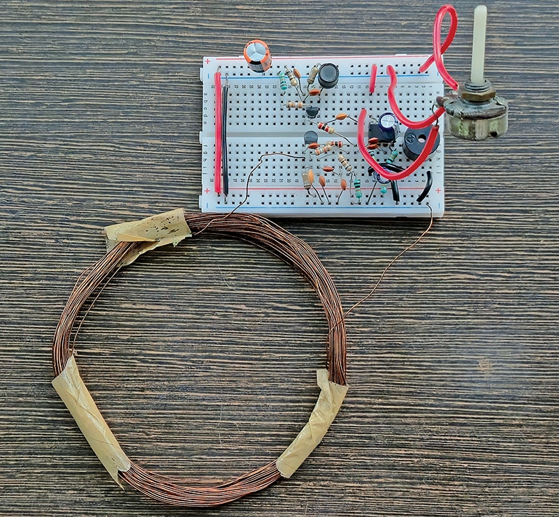
The circuit consists of two LC oscillators built using BC557 transistors, inductors, and capacitors. The search oscillator employs a 30-turn search coil wound with 30AWG enamelled copper wire on a former of approximately 10-centimetre diameter. This oscillator operates at around 153kHz. A second, identical LC oscillator serves as the reference oscillator and is also tuned to around 153kHz. Its frequency can be finely adjusted using a potentiometer to closely match that of the search oscillator.
The outputs of these two high-frequency oscillators are then mixed. Since their operating frequencies are nearly identical, the resulting difference, known as the beat frequency, falls within the audible range of human hearing. This low-frequency beat signal is amplified by an LM358 operational amplifier, which drives a piezo buzzer.

The circuit can be assembled on a breadboard and powered by either a 9V DC power supply or a 9V battery. Fig. 1 shows the author’s breadboard prototype.
| Parts List |
| Semiconductors: IC1 (IC1A- IC1C) – LM358 op-amp T1, T2 – BC557 PNP transistor Resistors (all 1/4-watt, ±5% carbon): R1, R4 – 18kΩ R2, R5 – 49kΩ R3, R6 – 680Ω R7, R8 – 2kΩ R9, R11 – 10kΩ R10, R12 – 100kΩ RV1 – 10kΩ preset Capacitors: C1 – 220µF, 25V electrolytic C2, C4 – 1nF ceramic disc C3 – 3.7nF ceramic disc C5, C6 – 10nF ceramic disc C7 – 2nF ceramic disc C8 – 10µF, 25V electrolytic Inductors: L1 – 30 turns of 30AWG wire wound over 10cm dia. non-metallic core L2 – 220µH radial inductor Miscellaneous: BT1 – 9V battery BZ1 – Buzzer – General-purpose PCB/breadboard – Connecting/jumper wires – Enclosure (optional) |
Circuit and working
The circuit diagram of the BFO metal detector is shown in Fig. 2. It is built around two BC557 PNP transistors (T1 and T2), an LM358 operational amplifier (IC1), a buzzer (BZ1), and a few passive components.
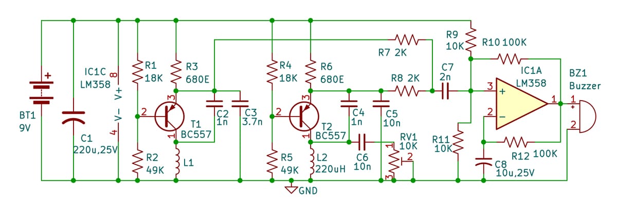
The circuit consists of three main sections: two independent Colpitts radio-frequency (RF) oscillators, a passive resistive mixer, and a single-supply audio amplifier. One oscillator functions as the search oscillator, while the other serves as the reference oscillator. Under normal conditions, both oscillators operate at nearly the same frequency. When a metallic object approaches the search coil, the frequency of the search oscillator changes slightly. The outputs of the two oscillators are mixed to generate a low-frequency beat (difference) signal, which is amplified by the LM358 and applied to the buzzer. The resulting change in audio pitch indicates the presence of metal nearby. The circuit operates off a 9V battery, and capacitor C1 reduces ripple while ensuring stable operation.