





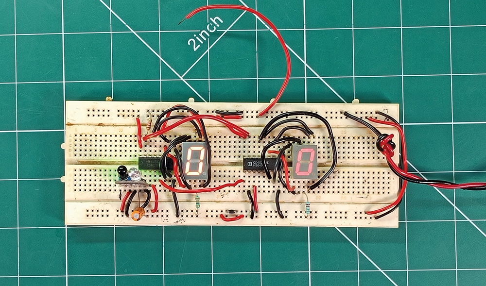
A people counter enables real-time occupancy monitoring, making it ideal to check occupancy in offices, factories, libraries, meeting halls, and other public spaces. The system presented here is a simple, reliable, and cost-effective people-counting solution based on an IR sensor and CD4026 decade counter ICs. Unlike microcontroller-based alternatives, this design is easy to construct, troubleshoot, and maintain, eliminating the need for programming. It is therefore well suited for beginners, educational demonstrations, and practical installations requiring a low-cost, dependable people counter. The author’s prototype on a breadboard is shown in Fig. 1.
| Parts List |
| Semiconductors: IC1, IC2 – CD4026B decade counter/7-segment driver Resistors (all 1/4-watt, ±5% carbon): R1 – 2.2kΩ R2, R3 – 330Ω Capacitors: C1 – 4.7µF, 25V electrolytic Miscellaneous: DIS1, DIS2 – 7-segment CC display (LTS6980HR/LTS543 S1 – Push-to-on switch CON1, CON2 – 2-pin connector – IR sensor module – Designed PCB or general-purpose board 16-pin IC base – 2 (optional) – Connecting wires – Enclosure/cabinet – Screws and spacers – 5V DC battery or adaptor for power supply |
Circuit and working
Fig. 2 shows the circuit diagram of the people counter using an IR sensor module. It is built around two CD4026 decade counter/7-segment driver ICs (IC1 and IC2), two common-cathode 7-segment displays (DIS1 and DIS2, such as LTS6980HR or LTS543), and a few other components.
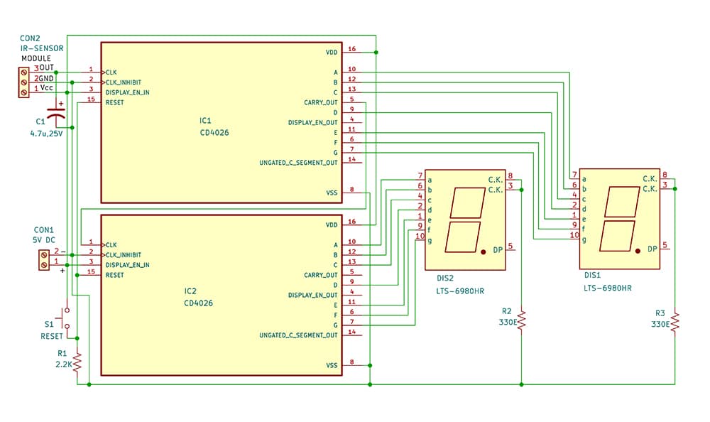
The two CD4026 ICs are cascaded to count and display numbers from 00 to 99. An IR sensor module detects the movement of a person passing through the entrance, and the count is displayed on the two 7-segment displays. Other components include a 2.2kΩ resistor (R1) for stable operation, 330Ω resistors (R2 and R3) for display current limiting, and a push-to-on switch (S1) for resetting the counter to zero.
IC1 drives the units digit display (DIS1), while its carry-out output is connected to the clock input of the second IC (IC2), which drives the tens digit display (DIS2). This cascading arrangement enables the circuit to count from 00 to 99. A reset switch (S1) simultaneously clears both counters and resets the display to zero.
Proper grounding and the use of current-limiting resistors ensure reliable operation. The sensitivity of the IR sensor can be adjusted using its onboard preset to achieve accurate detection and minimise false triggering. The entire circuit operates off a regulated 5V DC power supply or adaptor. The output of the 5V DC adaptor is connected to CON1 to power the circuit.
The people counter operates by detecting and counting digital pulses generated by the IR sensor. The IR sensor continuously emits infrared radiation and monitors its reflection. When a person passes in front of the sensor, the IR beam is interrupted, generating a digital pulse at its output. This pulse is applied to the clock input of the first CD4026 (IC1), causing the count to increment by one. Since the CD4026 incorporates a 7-segment decoder/driver, it directly drives the displays (DIS1 and DIS2). The maximum count displayed by DIS1 and DIS2 is 99. To extend the count to three or four digits, you may cascade three or four CD4026 ICs, respectively.
Construction and testing
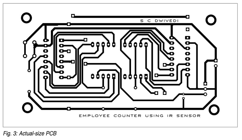
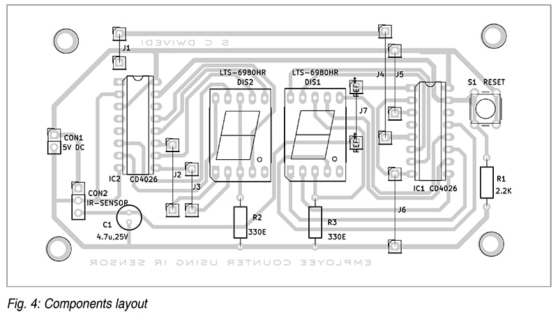
An actual-size, single-sided PCB layout for the people counter is shown in Fig. 3, and its component layout is shown in Fig. 4. After assembling the circuit on the designed PCB, mount it inside a suitable enclosure with proper openings for the displays, the reset switch, the connectors, and the IR sensor. Ensure that all power supply pins are connected correctly to +5V and ground. Alternatively, the circuit may be assembled on a general-purpose PCB if the designed PCB is unavailable.
Mount the displays DIS1 and DIS2, along with the reset switch (S1), on the front panel of the enclosure. Position the IR sensor module at a suitable height and angle so that it reliably detects a person crossing its path. The sensor output is connected to the clock input of the first counter IC (IC1), while the carry-out output of IC1 is connected to the clock input of IC2 for cascading operation. The outputs of both ICs are wired to their respective 7-segment displays using the correct pin configuration.
For testing, apply a regulated 5V DC supply to the circuit. Initially, both displays should show 00, indicating the reset condition. Move a hand or walk in front of the IR sensor to simulate entry detection. The count should increase by one for each detection. Continue testing to verify correct counting up to 99 and ensure that the tens digit increments correctly after every ten counts. Press the reset switch to confirm that the display returns to zero instantly. If the counter skips counts or behaves erratically, check the IR sensor alignment, verify all wiring connections, and ensure that the 5V power supply is stable and free from electrical noise.
Installation
Installation of this counter requires proper placement and mounting to ensure accurate operation. The system should be installed at the only entry or exit point, such as a main door or corridor, so that every person is counted without fail.
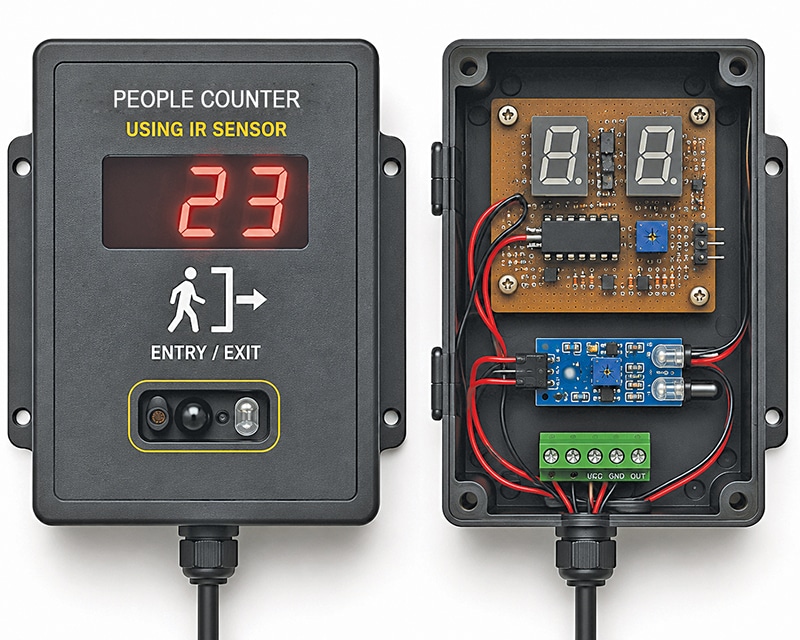
Mount the IR sensor at a height of approximately 90 to 120 centimetres on one side of the doorway, aligned with the expected path of movement. Ensure that the sensor is not exposed to direct sunlight or highly reflective surfaces, as these may cause false triggering. The display unit should be installed in a clearly visible location, such as the entrance or at a security desk, while the circuit should be housed in a suitable protective enclosure. A suggested wall-mounted enclosure with its internal view is shown in Fig. 5 for reference. However, a different enclosure may be selected to suit the installation requirements.
Use a regulated 5V DC power supply, preferably with surge protection or UPS backup, to ensure reliable operation. Before deploying the system, adjust the sensor sensitivity and test the setup by allowing people to pass through the doorway while verifying that the count is displayed correctly. For the best accuracy, ensure that only one person passes through the detection zone at a time. Periodically inspect the sensor alignment and keep the sensor surface clean to maintain consistent and reliable performance.
Bonus
You can watch the video of the tutorial of this DIY project below
S.C. Dwivedi is an electronics enthusiast and circuit designer at EFY
