






Modern Wi-Fi signals can do more than transfer data. These radio waves can be analysed using channel state information (CSI) to detect movement, estimate location, track activity, and even sense physiological signals. By extracting fine-grained amplitude and phase data across multiple subcarriers, CSI can potentially detect people, including through some obstructions; estimate their distance and approximate position relative to a router; track movement; recognise activities and falls; and monitor vital signs such as breathing rate. This turns ordinary Wi-Fi infrastructure into a contactless sensing platform for indoor monitoring, security, health, and navigation.
The design is centred on this capability and uses a minimal standalone circuit based on the ESP32-S3. Real-time CSI and signal-strength information are displayed on an OLED screen, with an option for a colour SPI LCD. Four switches and a potentiometer provide menu selection and control. The ESP32-S3 can be programmed through USB-C solder pads on the board or pre-programmed using a dedicated programmer jig before being mounted on the PCB.
The hardware is designed to accommodate the ESP32-S3 directly as an SMD component. The PCB includes footprints for commonly available displays and modules, so the display can be changed without redesigning the board. Internal PCB routing is preconfigured to support either an OLED or colour SPI LCD. The device also supports indoor navigation by providing real-time distance and approximate position information relative to an access point, along with continuous Wi-Fi scanning and passive monitoring and analysis.
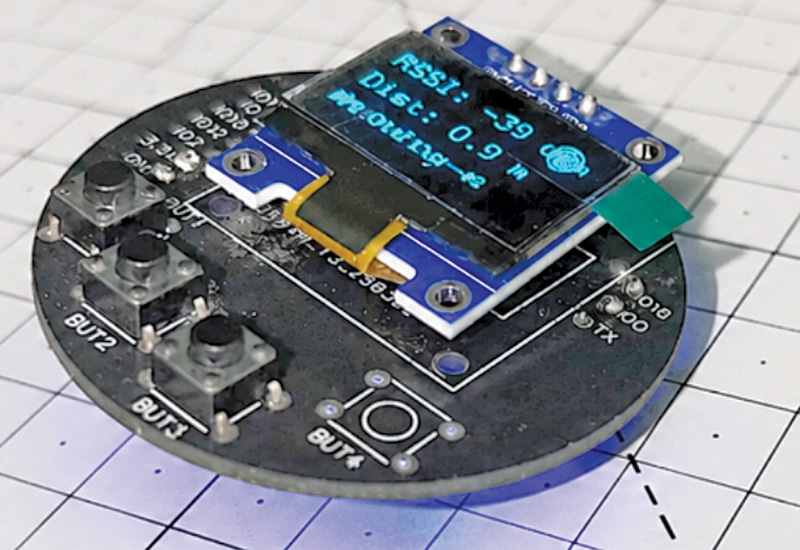
These features make it a compact and portable Wi-Fi sensing and analysis tool for indoor tracking, monitoring, navigation, and diagnostic applications. Fig. 1 shows the author’s prototype of the Wi-Fi tool. The components required to build the device are listed in the Bill of Materials table.

| Bill of materials | |||||
| Name | Designator | Footprint | Manufacturer part | Manufacturer | Qty |
| 100nF | C1 | C0805 | CC0805KRX7R9BB104 | YAGEO | 1 |
| 22µF | C2,C3 | C0805 | CL21A226MAYNNNE | Samsung | 2 |
| 10µF | C4 | C0805 | CL21A106KAYNNNE | Samsung | 1 |
| AMS1117-3.3V, 1A LDO regulator | IC1 | SOT-223-4_L6.5-W3.5-P2.30-LS7.0-BR | AMS1117-3.3 | UMW | 1 |
| ESP32-S3-WROOM | IC2 | WIRELM-SMD_ESP32-S3-WROOM-1 | ESP32-S3-WROOM-1-N8R8 | Espressif | 1 |
| TS3325A 250GF 025 | SW1 | KEY-SMD_4P-L3.1-W3.1-P2.00-LS4.0 | TS3325A 250GF 025 | Shou Han | 1 |
| TSC005A2518A | SW2, SW3, SW4, SW5 | SW-SMD_4P-L5.2-W5.2-P3.70-LS6.4 | TSC005A2518A | BZCN | 4 |
| USB-C solder-pad connector | U1 | USB-C solder-pad connector | — | — | 1 |
| SSD1306 OLED | U2 | SSD1306-OLED-128X64-I2C | — | — | 1 |
| 50kΩ potentiometer | U3 | RES-ADJ-SMD_RA1010N-1H-2016-B50K-000 | RA1010N-1H-2016-B50K-000 | G-Switch | 1 |
| GC9A01 | SPI | GC9A01 ROUND | 19192 | Waveshare | 1 |
Circuit and working
Fig. 2 shows the complete circuit of the Wi-Fi tool and indoor location tracking device. Power is supplied through the USB-C solder-pad connector, which provides 5V to the AMS1117, which is a 3.3V, 1A LDO regulator (IC1). The ESP32-S3-WROOM (IC2) is the main controller, handling Wi-Fi connectivity, CSI processing, and display and user-interface control.
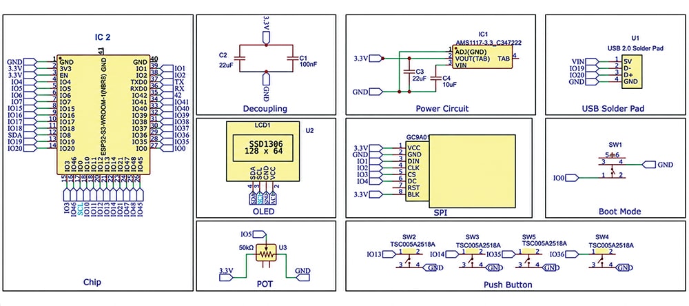
The regulator generates a stable 3.3V supply for the ESP32-S3 and other circuit sections. Capacitors C1 through C4 provide supply filtering and decoupling and are placed close to the regulator and ESP32-S3 for stable operation. The ESP32-S3 and display together consume less than 800mA when the ESP32-S3 operates in Wi-Fi AP or STA mode, leaving approximately 200mA of current margin.
The USB-C connector also provides D− and D+ connections to IO19 and IO20 of the ESP32-S3, respectively, for programming and debugging. Alternatively, the ESP32-S3 can be programmed off-board using a dedicated programming jig before mounting it on the PCB. A boot-control switch (SW1) connects IO0 to ground for programming-mode selection.
The PCB supports two display options. An SSD1306 128×64 OLED (U2) can be connected through the I²C interface using SDA and SCL, while a GC9A01 colour TFT display uses the SPI interface through DIN, CLK, CS, DC, RST, and BLK signals. The 50kΩ potentiometer is connected to IO5 and provides an analogue input for user control. Four tactile switches, SW2 through SW5, are connected to IO13, IO14, IO35, and IO36, respectively, and provide menu selection and navigation.
During operation, the ESP32-S3 receives Wi-Fi signals, acquires and processes CSI data, and displays the relevant signal, sensing, or indoor-location information on the selected display. All signal and power connections are routed through the PCB to form a compact standalone Wi-Fi sensing and analysis tool.
PCB design
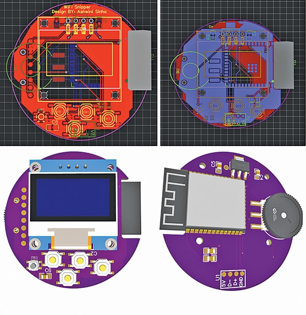
The PCB is designed as a compact circular board, with the display and user-interface controls placed on the top side for easy access. The remaining components, including the ESP32-S3 module and 50kΩ potentiometer, are mounted on the bottom side. This arrangement allows the device to be rotated with the thumb while the controls are operated with the same hand.
The board supports both the SSD1306 OLED and GC9A01 colour TFT displays, allowing either display to be fitted without redesigning the PCB. Fig. 3 shows the top and bottom PCB layouts and their corresponding 3D views of the Wi-Fi tool and indoor location tracking device.
Software and code
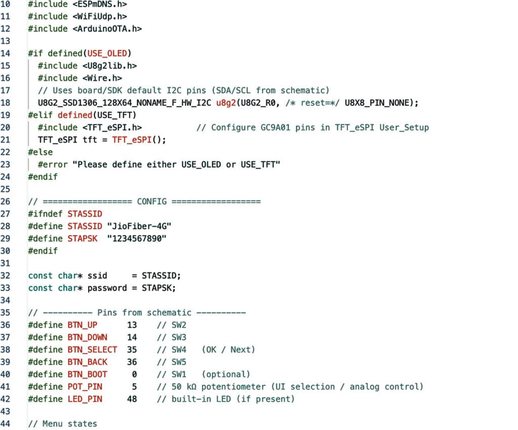
The software is developed for the ESP32-S3 using the Arduino framework and Arduino IDE. The program uses the WiFi.h library for Wi-Fi connectivity, ESPmDNS.h for network name resolution, and ArduinoOTA.h for over-the-air firmware updates. It supports two display options: an SSD1306 128×64 OLED using the I²C interface through the U8g2lib.h library, and a GC9A01 colour TFT using the SPI interface through the TFT_eSPI.h library. Conditional compilation using USE_OLED or USE_TFT allows either display to be selected at compile time. The Wi-Fi SSID and password are defined in the configuration section and used by the ESP32-S3 to establish a network connection.
The code also defines the GPIO pins for the user interface according to the circuit diagram. Buttons SW2, SW3, SW4, and SW5 are connected to IO13, IO14, IO35, and IO36, respectively, and are used for menu navigation and selection. SW1 is connected to IO0 for boot/programming control, while the 50kΩ potentiometer is connected to IO5 to provide an analogue input for user control. After startup, ESP32-S3 initialises the selected display, connects to the Wi-Fi network, and performs the required sensing and signal-processing functions. Fig. 4 shows the code snippet for configuring Wi-Fi.
The processed Wi-Fi signal and CSI information can then be displayed on the selected OLED or TFT screen, while the switches and potentiometer provide user input. The OTA library allows firmware to be updated wirelessly without a physical connection to the device.
Construction and testing
After all the components are assembled on the PCB, a battery can be connected to the battery-connector solder pads to power the device. The OLED initially displays ‘Trying to connect’ while the ESP32-S3 establishes a Wi-Fi connection. Once the connection is established, the main user interface appears, displaying a menu of available functions.
The up and down buttons are used to navigate through the menu and select the required function. The device provides options for viewing the CSI report, scanning nearby Wi-Fi networks, measuring the approximate distance from a selected access point, and performing Wi-Fi analysis. During testing, the SSD1306 OLED successfully displayed the Wi-Fi connection status, menu options, detected networks, RSSI values, and estimated distance. An RSSI of -35dBm corresponded to an indicated distance of approximately 0.6m in the test setup.
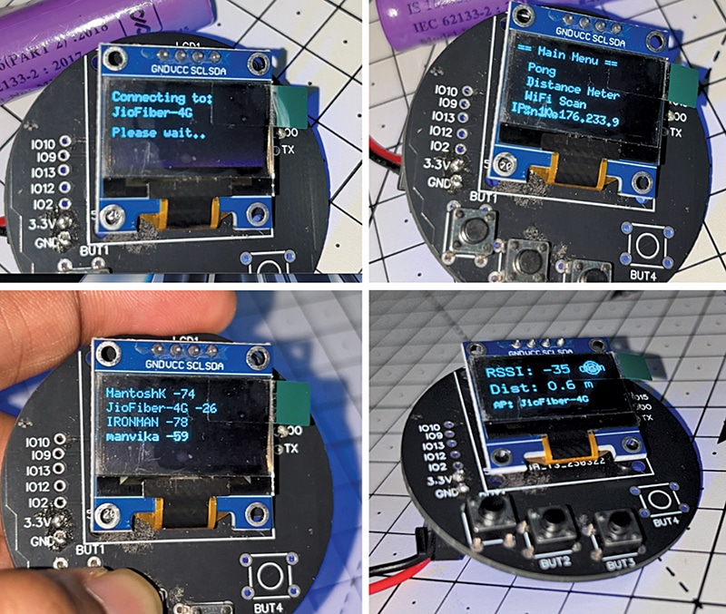
The four push-buttons were tested for menu navigation and selection, while the potentiometer provided additional user input. These tests confirmed the operation of the assembled PCB, OLED display, user controls, Wi-Fi connectivity, and sensing functions, as shown in Fig. 5.
Ashwini Kumar Sinha, an IoT and AI enthusiast, is Tech Journalist at EFY.

