




Thermal interface materials, cold plate design, coolant flow, and simulations help engineers manage heat and reliability in AI chips.
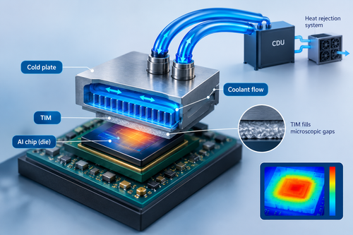
Thermal interface material (TIM) remains a key bottleneck in cooling high-power artificial intelligence (AI) chips, even in liquid-cooled systems. It fills microscopic gaps between the silicon die and the cold plate, helping heat move away from the chip. However, the material’s thermal resistance can limit heat transfer.
In a recent conversation, Ajay Sekar, thermal engineer at NVIDIA, explained how engineers identify heat transfer limitations in a cooling system. In direct-to-chip liquid cooling, heat travels from the silicon die through the TIM to a cold plate. The coolant carries it to a coolant distribution unit (CDU), which transfers it to the facility-level heat rejection system.

Engineers use thermal resistance networks to assess conduction through solids and convection between solid surfaces and fluids. A heat spreader, or lid, can distribute heat from a small chip area across a larger surface. Copper is commonly used, while copper alloys and aluminium may suit specific applications.
The difficulty is compounding as AI processors consume more power and advanced packaging places chips side-by-side or vertically, creating local hotspots. Ajay said, “Leakage power can double with every 10°C rise in temperature. Cooling is also needed for voltage regulators, driver metal-oxide-semiconductor field-effect transistors (MOSFETs), controllers and inductors, which generate heat despite limited circuit-board space.”
High power density can affect reliability through electromigration, material expansion and contraction, fluid leaks, and TIM pumping out of the gap between a chip and its cooling hardware.
Ajay said, “Air cooling can become insufficient at heat fluxes of around 40–50 W/cm² at component level, while rack cooling can become difficult above 20–30 kW. These are rules of thumb; cooling choices also depend on space, cost, serviceability, and mechanical constraints.”
Cold plate design involves balancing fin thickness, spacing, height, and material against heat removal and pressure drop. Narrow fin spacing can increase pressure drop and clogging risks, while uneven coolant distribution can create hotspots. Coolant temperature and flow rate also involve trade-offs: warmer coolant may reduce energy used for chilling, but requires higher flow.
Engineers use computational fluid dynamics (CFD) to model temperature, fluid velocity, and pressure drop, validating simulations through energy and mass balance checks, mesh-independence tests, and thermal-resistance comparisons. Testing uses application-specific workloads and measures junction temperature, power, coolant inlet temperature, flow rate and pressure drop.
Emerging approaches include two-phase cooling, AI-designed cooling structures, and microfluidic channels beneath hotspots. However, manufacturing cost, contamination, reliability, integration, and the need for application-specific training data remain challenges. Ajay advised young engineers to strengthen their fundamentals, learn computational fluid dynamics (CFD) tools, and follow cooling research through technical papers and trade publications.