


This generation (Gen Y, born between the 1980’s and the year 2000) constantly gets bored. It is forever looking for something new and exciting, and everyone is willing to try different things as long as they can derive a good experience out of it. Be it in any field, it is difficult to stand out today simply because of the problem of plenty. Looking at the website of Proteus, I must say they are taking this aspect seriously.
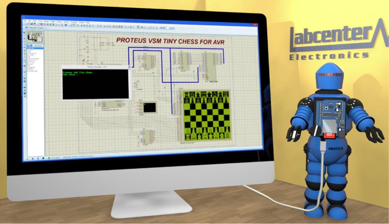
Proteus design suite is a package put together by Labcenter Electronics to give you a novel simulation and printed circuit board (PCB) designing experience. What makes this tool special? What new does it have to offer? Read on to know.

Proteus design kit has about 785 microcontroller variants ready for simulation, straight from the schematic. Be it Atmel, Microchip or ARM, once you get a hang of the tool, you need not worry about the impending platform. Let us begin by considering one of the most popular microcontroller kits among students, Arduino.

Visual Designer for Arduino
Visual Designer in Proteus takes a cue from Arduino itself, removing the lower-level complexities of software language and hardware design. It uses a combination of its trademark Virtual System Modeling simulation—which we will come to later—flowcharts and virtual hardware, resulting in an integrated and intuitive development environment for Arduino.

Depending on the device you want to connect to Proteus, you can configure the peripheral accordingly and use high-level methods to control it. If you are attaching, say, a robot, you might need different peripherals for the various sensors, one for the wheels and another for the motor. The corresponding microcontroller is automatically updated with connection details.
Visual Designer allows you to set breakpoints at which you need to debug the course of the robot and perform simulations around it. To help you get started, the kit provides ready-to-use Arduino shields, breakout boards and sensors in its peripheral gallery. Transferring the data to Arduino board simply requires plugging in the programming cable, making the required configurations and clicking to transfer the flowchart into the board. PICs can be simulated in real time, letting you test circuit functionality effectively.
Shortened lifecycle from schematic to PCB
It is VSM simulation that brings in Agile development into the embedded workflow, enabling you to quickly put together a prototype with hardware and firmware components. The inbuilt processor model is built to fully simulate input/output ports, interrupts, timers, universal synchronous/asynchronous receiver/transmitters and all other peripherals present on each supported processor.
Giving you the flexibility to interact with your design using onscreen indicators such as LCD and LED displays, and actuators, you can apply your firmware to the microcontroller of your choice and co-simulate the program within a mixed-mode simulation program with integrated circuit emphasis (SPICE) circuit simulation. If coding is your forte, take the design flowchart back to its Arduino C++ code, or convert it to an Arduino sketch and play with the code.
A resourceful kit. Proteus design kit contains thousands of common parts you would need. It allows you to import more using BSDL format. The physical and electrical designs can be viewed as grids, paving the way for easier cross-probing and component or net selection. Hierarchical designs and system level designs are just a few clicks away.
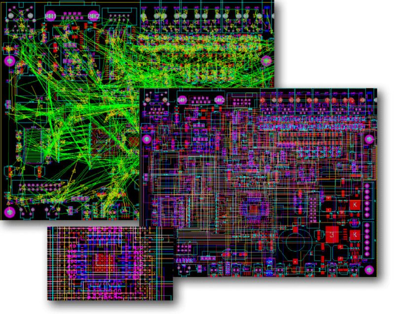
A powerful PCB design suite
Combining the schematic capture and ARES PCB layout programs, this design suite targets PCB designs with a professional touch. The next section discusses a few of the stand-out features of this layout designer.
In addition to these, the tool supports 16 copper layers, 10nm resolution and any angle placement. There is also support for power planes, letting you place polygonal regions within which inner boundaries are automatically created around existing pads and tracks.
Intelligent routing. The wiring process is intuitive. Called Follow-Me Routing, the control is in your hands, giving you the best-fit route within designated constraints. As you move the mouse, so does the wiring, linking together the parts of your schematic. And once a base is done, you can create a design snippet to import into a future project.
The snippet can range from a simple rectifier circuit to the modelling of a USB engine, or can simply be a template containing basic layout information like boundaries and holes. It goes without saying that schematic hierarchies and logic schematic designs are fully supported by the tool.
Go the manual way… The one thing layout designers have a tough time getting right is congestion release—tight spaces with too many wires that can neither be re-routed easily nor done without. It is a matter of trial and error, a process that is eased a bit in Proteus by letting you add via connections to pads, aka surface mount technology.
Manual routing can also create curved tracks by holding down ctrl key, and thick tracks are automatically necked to fit in with the set rules. You can also logically or globally control the size and diameter of teardrops, as required. To make sure you do not violate rules, a live status for connectivity and design rules can be found at the bottom of the screen.
… Or exploit the auto feature. What the auto-router gives you is flexibility. How is that? Because auto-routing is shape based. A quick and an easy fix to your design rule violations! Using advanced cost based conflict-reduction algorithms proven to maximise completion rates on even the most densely-packed boards, the router gives you the best routing possible under given circumstances. Advanced-level users also drive the router either by writing custom routing scripts or by directly entering routing commands interactively, to route particular areas or specify fan-out criteria.
Handling large numbers of pins
Schematic Capture is designed to aid a high degree of control over the drawing appearance, be it line widths, fill styles or fonts; extending this to the layout graphics, too. Dealing with a ball-grid array or a high pin count device can be tricky. The sheer volume complicates everything from connection to routing.
To handle this easily, Proteus lets you first bring in the component definition directly from the manufacturer’s boundary scan description language file. You can then split these into smaller, more manageable elements using a component separator option, or even re-arranging the pins, while preserving boundary scan description language file as it is.
PCB layout uses LPC standard footprint, but you can create your own custom footprint using tools like PCB Library Export and import the pad’s ASCII format into Proteus. If being used in a field-programmable gate array, change in pin-mapping can be loaded into the package tool and then used to update Proteus with the latest details. The only requirement is that the PCB net classes and design rules should be set up before starting with the layout, so as to keep the tool informed of the next alpha traces and aid manoeuvring between high pin devices.
Design rules can also be custom-generated according to the entire design for net classes, trace and via styles, clearances and more. At pre-production stage, the PCB tool runs a quality-assurance check, checks for power plane geometry and integrity, and tests to spot common design errors.
The bombarded view and the BOM
A 3D viewer lets you see your PCB in all its fullness. Apart from simply looking at your board from a 3D viewpoint, this feature can strip down the design to a bare board, letting you inspect tracks and vias or zoom in on a specific part. With built-in standard for the exchange of product model data and initial graphics exchange specification support, you can import these models to view your components in 3D and export your whole board at the end, to use with any mechanical computer-aided design tool.
The thing about bill of materials (BOM) in Proteus is the fact that it is fully customisable. You can work with multiple components at once and, more importantly, generate it in the style used by the company in question.
Kicking grounds backstage
Proteus has been put to good use in various industry segments, right from design to verification. Electronic airfield ground equipment, underground pipeline corrosion engineering, vehicle dashboards, musical instrument digital interface converters and Hi-Z USB audio interfaces, truck braking systems and industrial elevators are some of the areas Proteus has found its way into.
With features and flexible licensing, Proteus is also an in-demand tool at colleges to aid courses dealing with electronics, microcontrollers and PCB designing.
Proteus Lite is a shareware-licensed tear-down version of the original, providing limited but meaningful functionality. Built for Windows, Proteus 8.5 is the latest release from the team that is making a presence at major conferences.
Commercial licences for tool usage can be obtained at www.labcenter.com/purchasing. Get an instant online quotation according to the level of advancement you require, and take it from there; have the kit delivered at your doorstep.
For more information, visit their official website
Priya Ravindran is M.Sc (electronics) from VIT University, Vellore, Tamil Nadu. She loves to explore new avenues and is passionate about writing
Can you develop ADC circuit design
Dear Admin.
how to configure the inductance (Primary and Secondary) to get 15VAC, 3A from the Vsine (alternator) source 220V, 50Hz.
I’m using Proteus 8.3 student edition. the transformer in simulation :TRAN-2P2S.
Thank you very much for your help.