


 The circuits for musical lights available in the market are highly expensive and based on microcontrollers. Also, their programming is very difficult. Here is a simple and cheap circuit for a musical light that you can build easily.
The circuit presented here is of an electric lamp flasher that flashes with music. It uses ten 60W, 230V AC bulbs. These bulbs glow in accordance with the amplitude of the audio signal. The circuit is built around 5-dot dual LED level meter driver IC KA2281 (IC1), pnp transistor BC557 (T1 through T10), triac BT136 (triac1 through triac10) and some discrete components.
The IC KA2281 has two audio inputs. It is used in audio level indicators with operating voltage ranging from 5V to 14V. Features include high input impedance with externally adjustable gain of input amplifier.

It is an active-‘low’ IC. When the amplitude of the input increases, the respective driver pins of IC KA2281 go low. These pins are connected to transistors, which act as switches and turn on respective triacs. Triac1 through triac10 are used to turn the bulbs (B1 through B10) ‘on’. Input to the circuit is given from an amplifier.
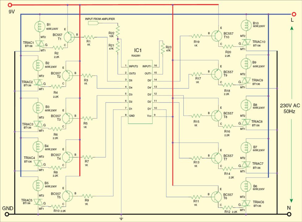
The working of the circuit is simple. Connect the input from the amplifier to the circuit. According to the amplitude of the audio signal, the output pins of IC1 go low, transistors T1 through T10 conduct to fire triac1 through triac10 and respective bulbs (B1 through B10) glow. Bulbs B1 through B10 turn on when corresponding output pins of IC1 go low.
All the emitters of transistor T1 through T10 are connected to the positive terminal of the power supply and the collectors of transistors are connected to the gates of triacs. So when pnp transistor T1 conducts, bulb B1 glows. Similarly, when T2 conducts, bulb B2 glows and so on.
In brief, the bulbs (B1 through B10) glow depending on the amplitude of the music. Connect the power supply line (L) of mains to bulbs (B1 through B10) and neutral (N) to MT1 terminals of triac1 through triac10.
Assemble the circuit on a general-purpose PCB and enclose in a small plastic cabinet keeping the bulbs at the circumference. Use bulb holder for all the bulbs. Also use an IC socket for IC KA2281. Fix the mono socket for connecting the input from the audio amplifier.
The circuit works with a 9V battery. In place of the battery, a 9V, 500mA AC adaptor can also be used to power the circuit.
EFY warning. While assembling, testing or repairing, take care to avoid lethal electric shock.