


We built this Arduino-based Digital Thermometer for temperature measurement applications.
Thermometers have been useful for temperature measurement for a long time. A digital thermometer is an electronic device used for accurate temperature measurement. Unlike traditional analog thermometers, which use mercury or other liquids, digital thermometers utilize electronic sensors to detect and display temperature readings.
Digital thermometers are commonly employed in healthcare settings for monitoring body temperature. They are also valuable in the food industry to ensure proper cooking and storage temperatures. Additionally, they are used in environmental monitoring to measure ambient temperatures in various settings.

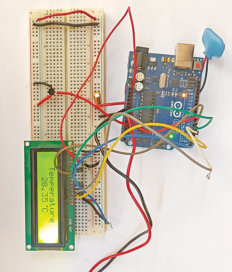
Digital thermometers offer convenience, accuracy, and ease of use, making them a popular choice for a wide range of temperature measurement applications. The author’s prototype of an Arduino-based digital thermometer on a breadboard is shown in Fig. 1.
| PART LIST for Digital Thermometer | |
| Semiconductors: | |
| IC1 | – LM35 temperature sensor |
| Resistors (all 1/4-watt, ±5% carbon): | |
| R1 | -1-kilo-ohm |
| R2 | -220-ohm |
| Capacitors: | |
| C1 | -4.7μF, 25V electrolytic |
| Miscellaneous: | |
| BOARD1 | -Arduino Uno board |
| LCD1 | –16×2 LCD display |
| CON1 | -2-pin connector |
| -Jumper wires (15 no.) | |
| -9V battery/9V adaptor | |
Arduino-based Digital Thermometer – Circuit and Working
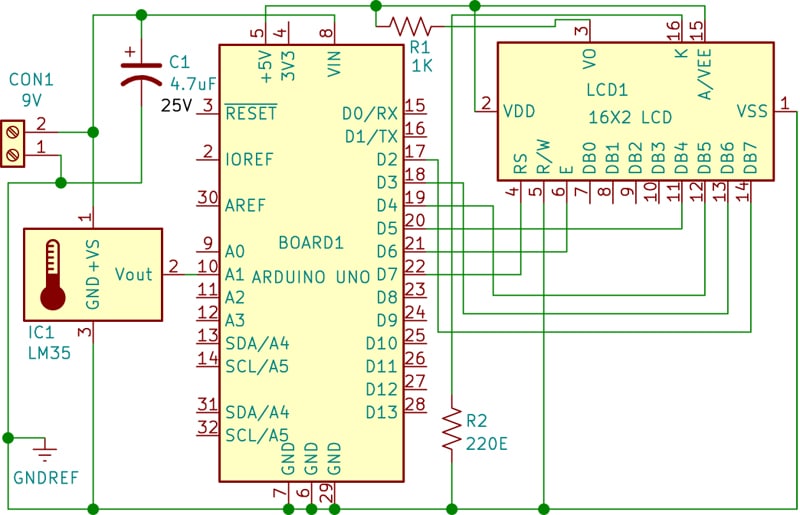
The circuit diagram of the thermometer is shown in Fig. 2. The thermometer is built around an Arduino board (BOARD1), a temperature sensor LM35 (IC1), a 16×2 LCD (LCD1), and a few other components. Simply connect a 9-volt battery or adaptor to the board to operate it.
The LM35 is an analog temperature sensor that outputs a voltage proportional to the temperature. The Arduino processes this information to display the temperature on the LCD.
The LM35 temperature sensor is used to sense the environment’s temperature, producing a signal that indicates a 1-degree temperature change for every 10mV change at its output pin. For example, if the output voltage of the LM35 sensor is 250mV, it means the temperature is around 25 degrees Celsius.
Arduino reads this output voltage of the temperature sensor using Analogue pin A1 and performs calculations to convert this analog value to a digital value representing the current temperature. After these calculations, the Arduino Uno sends the temperature signal to the 16×2 LCD using appropriate commands.
In this thermometer, the Arduino is used to control the entire system. Arduino is an open-source hardware platform for development purposes that runs on an ATmega controller.
The 16×2 LCD is widely used in embedded systems because it is cheap, readily available, small in size, and easy to interface. It consists of two rows and 16 columns, meaning it has 16 blocks of 5×8 dots. It requires 16 pins for connections, including 8 data bits (D0-D7) and 3 control bits (RS, R/W, and EN). The remaining pins are used for supply, brightness control, and backlight.
Arduino Code for Digital Thermometer
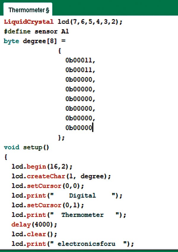
The code for temperature measurement using LM35 is described here. A library for the LCD unit is included and then data and control pins for the LCD and temperature sensor are defined. After obtaining an analog value at the analog pin, that value is read using the Analogue read function and stored in a variable. Then, the value is converted into temperature by applying the relevant formula. A snippet of the source code is given in Fig. 3.
Construction and Testing
First, upload the source code into the Arduino Uno board after selecting the board and port.
Then, assemble the circuit on a breadboard. Make the connections carefully as shown in the schematic in Fig. 2. The 16×2 LCD unit is directly connected to the Arduino Uno board in 4-bit mode. Data pins of the LCD, namely RS, EN, D4, D5, D6, D7, are connected to Arduino digital pins D7, D6, D5, D4, D3, D2.
The output of the temperature sensor LM35 is connected to Analogue pin A1 of the Arduino Uno, which generates 1 degree Celsius temperature for every 10mV output change at its output pin. The 9V battery or 9V adaptor is connected to the Arduino Uno board. The digital thermometer is ready to use.
Check other Digital Thermometer Projects
- Digital Thermometer using Op-amp
- Industrial Digital Thermometer
- Wireless Digital Thermometer For Multiple Sensors
- Digital Thermometer-Cum-Controller
- Thermometer Reference Design
Recommended: Explore our extensive collection of Arduino projects.
Bonus: You can watch the step-by-step video tutorial of this DIY project below: