
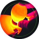
 Candling eggs, while they are incubating, is the proven method to test them for fertility. Often, egg candling is done using a light source to channel enough light into the egg in order to determine whether the egg is developing into a chick (see Fig. 1). The light source is usually an incandescent lamp or an LED. Many users prefer an LED as it does not create enough heat to harm the egg.
Here we describe a battery-powered LED egg candler to detect embryonic development or separate eggs with cracked shells. Being battery-powered, the egg candler can be taken anywhere. Also, it is more convenient to use: Just put the egg on the egg base and observe for embryonic growth.
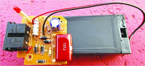
The author’s prototype is shown in Fig. 2.
Circuit and working
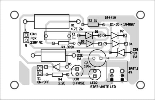
The circuit (shown in Fig. 3) has a 4V lead-acid SMF battery (BATT.1) and a 1-watt star white LED (LED2) on the right side. On the left side is a transformerless power supply to charge the battery. That is, the battery charger is powered by 230V AC mains supply through a transformerless circuit. A 5V Zener diode (ZD1) is used as a pre-regulator to protect low-voltage circuit components from damage by the high-voltage input.
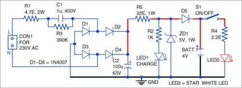
LED1 is the ‘charger on’ indicator. A 1-kilo-ohm resistor (R2) limits the working current of LED1, while a 2.2-ohm resistor (R4) controls the current flowing through LED2. A 4.7-ohm resistor (R1) is used as the inrush current limiter, and a 390-kilo-ohm resistor (R3) across 1µF capacitor (C1) works as the bleeder resistor.

The transformerless power supply offers advantages of low cost and light weight. Also, it is reliable when operating with nominal load.
Construction and testing
A PCB layout of the egg candler is shown in Fig. 4 and its components layout in Fig. 5. Link the battery to the star white LED (LED2) to generate the requisite light output. LED2 lights up when on/off switch (S1) is closed.

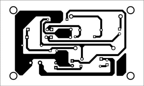
Download PCB and component layout PDFs: click here
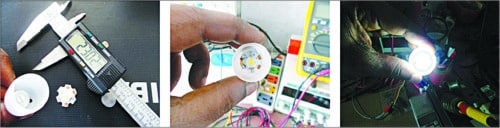
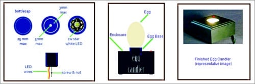
The egg base is made using a small bottle cap (23-25mm diameter) modified to suit the needs. A hole is made at the bottom of the cap for the wires of star white LED to pass through (Fig. 6). Besides, a small screw is fitted through another hole with washer and nut for the purpose of mounting later. Glue LED2 to the cap.
The finished egg base can be affixed to the top of a wooden/acrylic box with the circuit board (and battery) attached to the inner bottom of the enclosure. Refer Fig. 7 for mechanical design outline starting from the bottle cap to the proposed finished enclosure. The egg base prepared by the author is shown in Fig. 8.
After successful construction and initial testing, your home-made egg candler is ready for periodic candling of eggs.
Caution
Beware, any experiment involving 230V AC mains voltage demands extreme care and absolute respect for electrical safety guidelines!


