
A DC motor is normally operated by direct current. It converts the electrical energy into mechanical energy. This rotational movement is the source of required power to run many applications in Industry. Speed control is the critical function for motor operation. With speed control of the motor, we can alter the speed of the motor according to the desire of the application. It is deployed in many real-time applications like controlling robotic vehicles, paper mills, and elevators.
DC Motor
DC motor is a rotational device which converts electrical energy in the form of Direct Current into mechanical energy in the form of rotational motion of the motor shaft. The speed of the DC motor can be controlled by varying DC voltage. For applying changing voltage, the PWM technique is useful.
Construction and Working
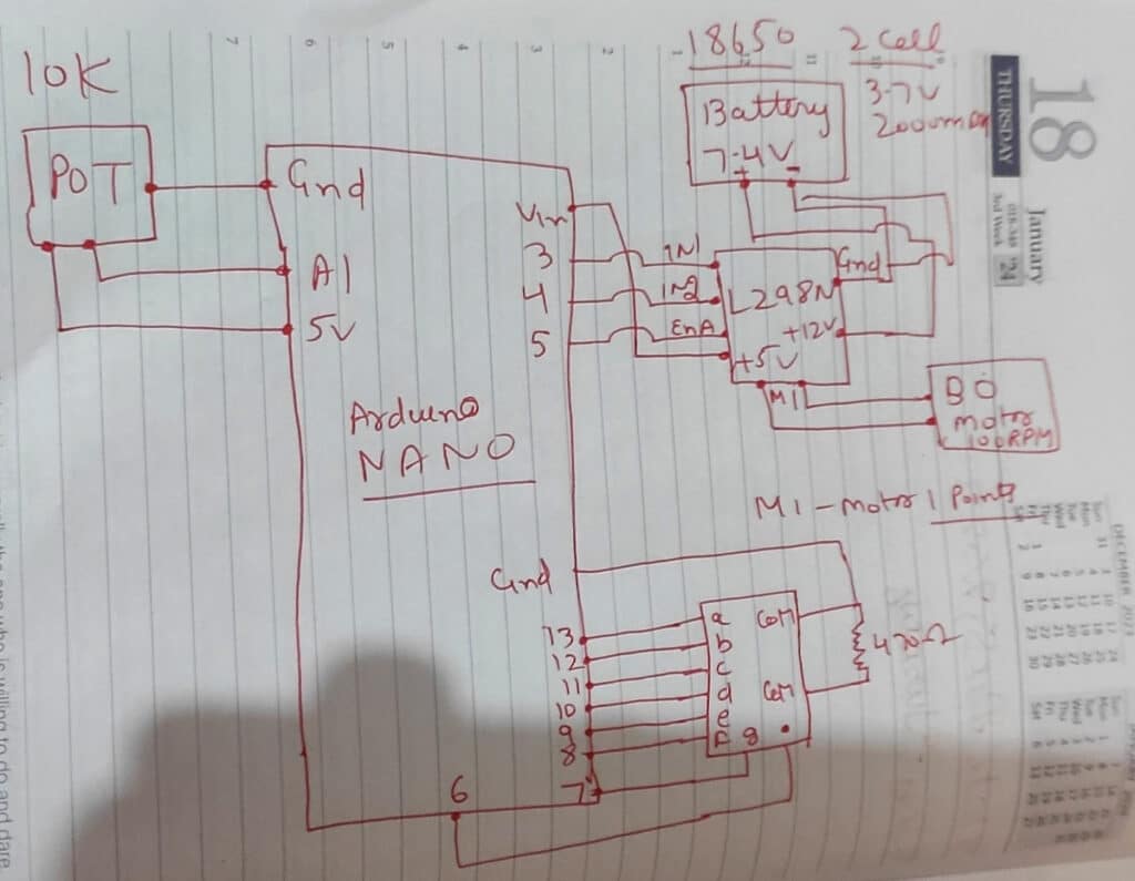
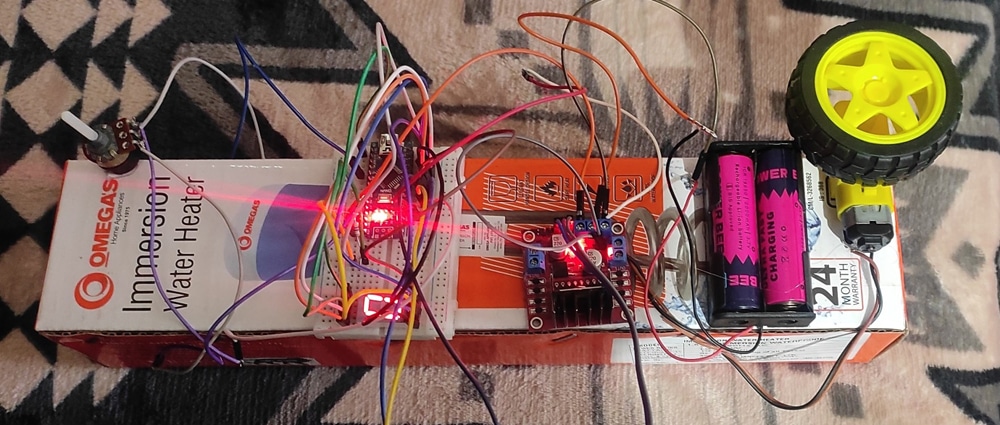
This circuit is built on a breadboard. This design is based on Arduino Nano Technology. It comprises Arduino Nano, L298 Motor Driver, Potentiometer 10K,1 Seven segment display, BO Motor 100 RPM, GearBox, Shaft, Battery Holder, Battery 18650 Li-on Cell 3.7V 2000mah (2 cell). Potentiometer has 3 pins – one is connected to GND, one is connected to 5V and the middle pin is connected to A1(analog pin). Seven segment pins a to g connected from pin 13 to Pin 7 and the decimal pin connected to 6. This is a common cathode 7-segment display with 2 common pins connected to GND. Pin 5 of Arduino Nano is connected to Enable Pin A of the L298 Motor Driver. Pin 3, and Pin 4 are connected to IN1 and IN2 of L298 Motor Driver. Attach BO Motors to motor pins of L298 Motor Driver and put wheels inside gearboxes. Motors can be controlled through a potentiometer and speed is displayed on a seven-segment display in RPM.

Arduino Nano
The Arduino Nano is a micro-size, complete, and breadboard-compatible board based on the ATmega328. The Arduino Nano can be powered via the Mini-B USB connection. The power source is automatically selected to the highest voltage source. The ATmega328 has 32 KB. Each of the 14 digital pins on the Nano can be used as an input or output, using pinMode(), digitalWrite(), and digitalRead() functions. They operate at 5 volts. Each pin can provide or receive a maximum of 40 mA and has an internal pull-up resistor.
L298 Driver:
This L298N Based Motor Driver Module – 2A is a high-power motor driver perfect for driving DC Motors and Stepper Motors. It uses the popular L298 motor driver IC and has the onboard 5V regulator which it can supply to an external circuit. It can control up to 4 DC motors, or 2 DC motors with directional and speed control. This L298N Motor Driver Module – 2A is perfect for robotics and mechatronics projects and perfect for controlling motors from microcontrollers, switches, relays, etc. Perfect for driving DC and Stepper motors for micro mouse, line-following robots, robot arms, etc.
Potentiometer 10K
Potentiometers are helpful in controlling the various electrical parameters of a circuit. This is a one-turn 10k Potentiometer with a rotating knob facility. This potentiometer is used to change the resistance between 0 to 10k ohms value by simply rotating the knob. The shaft is 15mm in length with a total resistance of 10K ohm.
Seven Segment Display
In modern times, seven-segment displays are commonly used in display systems for various applications. Seven-segment displays are made up of LEDs. These are used to display numbers like the status of petrol in vehicles, time in digital watches, display speed of vehicles, speed of washing machines, AC and various types of panels. The seven-segment display contains 7 leds to display numbers. You can display numbers from 0 to 9 on a single seven-segment.
Common Cathode Seven-Segment Display
- For the common cathode, connect common pins of 7 segments to the GNDpin of Arduino Nano.
- Connect +5 volts pin of Arduino Nano to decimal point pin in series to a 470 ohm- resistor to limit the current. It will glow.
- In the Common cathode, a,b,c,d,e,f,g, and h pins of the segment display are connected to Arduino Nano pins which can be controlled via programming by assigning values.
Part List
Arduino Nano, L298 Driver, BO Motor 100 RPM, Common cathode Seven Segment Display, Potentiometer 10K,Tyre, Bread Board, Jumper Wires, USB Cable, Cardboard Box, Battery Holder, Battery Module 18650 3.7V 2000mah (2 cell)
Software
Programming of the project is done on an Arduino 1.8.19 tool. The Potentiometer 10k module is connected to an Arduino Nano analog pin A1, 1 pin connected to 5V of Arduino Nano, 1 pin is connected to GND of Arduino Nano. Pin 5 of Arduino Nano is connected to Enable Pin A of L298 Motor Driver. Pin 3, Pin 4 are connected to IN1 and IN2 of L298 Motor Driver. Attach BO Motor 100 RPM to motor pins of L298 Motor Driver and put wheel inside gearbox. Through Software, Potentiometer sends analog signal to A1 pin and accordingly Arduino Nano sends commands to L298 Motor Driver which in turn sends commands to Motor to run according to the value of potentiometer.
Testing
Make connections as per the circuit diagram. Give voltage from Battery Holder 18650 Li-on Cell 3.7 V 2000 mah(2 cell – 7.4V). Check the status of seven-segment display if zero is displaying on it. Move the knob of potentiometer 10K and record the speed displayed in RPM from 0 to 9 RPM. Here 0 means 0 RPM and 9 means 90 RPM and a single dot on seven-segment display means maximum speed 100 RPM. Observe the speed of BO DC Motor according to the rotation of Knob (0-255). Value 0 from potentiometer means 0 RPM(revolution per minute-minimum speed), value 255 refers – 100RPM(maximum speed). This prototype can be extended to 2 or more motors with additional seven-segment display or LCD display with direction control of DC motor for various robotics and industrial application.
int seg_Pins[] = {13, 12, 11, 10, 9, 8, 7, 6}; // { a b c d e f g . )
int pot_map;
int pot_input;
////MOTOR1 PINS
int ena = 5;
int in1 = 3;
int in2 = 4;
byte seg_Code[11][8] = {
  //  a  b  c  d  e  f  g  .
  { 1, 1, 1, 1, 1, 1, 0, 1},  // 0
  { 0, 1, 1, 0, 0, 0, 0, 0},  // 1
  { 1, 1, 0, 1, 1, 0, 1, 0},  // 2
  { 1, 1, 1, 1, 0, 0, 1, 0},  // 3
  { 0, 1, 1, 0, 0, 1, 1, 0},  // 4
  { 1, 0, 1, 1, 0, 1, 1, 0},  // 5
  { 1, 0, 1, 1, 1, 1, 1, 0},  // 6
  { 1, 1, 1, 0, 0, 0, 0, 0},  // 7
  { 1, 1, 1, 1, 1, 1, 1, 0},  // 8
  { 1, 1, 1, 1, 0, 1, 1, 0},  // 9
  { 0, 0, 0, 0, 0, 0, 0, 1}   // .
};
void setup()
{
  pinMode(A1, INPUT);
  pinMode(ena, OUTPUT);
  pinMode(in1, OUTPUT);
  pinMode(in2, OUTPUT);
   for (int i = 0; i < 8; i++)
  {
    pinMode(seg_Pins[i], OUTPUT);
  }
  Serial.begin(9600);
}
void loop()
{
  pot_input = analogRead(A1);
  pot_map= map(pot_input, 0, 1023, 0 , 255);
  //Serial.println(pot_input);
  Serial.println(pot_map);
  delay(300);
if ((pot_map > 1) && (pot_map <= 25))
  {
  digitalWrite(in1,LOW);
  digitalWrite(in2,HIGH);
  analogWrite(ena, pot_map);
   for (int n = 1; n < 2; n++)
   {
    display_Digit(n);
    delay(2000); ///2 second delay
  }
  }
  else if ((pot_map > 25) && (pot_map <= 50))
  {
  digitalWrite(in1,LOW);
  digitalWrite(in2,HIGH);
  analogWrite(ena, pot_map);
   for (int n = 2; n < 3; n++)
  {
    display_Digit(n);
    delay(2000); ///2 second delay
  }
  }

 else if ((pot_map > 50) && (pot_map <= 75))
  {
  digitalWrite(in1,LOW);
  digitalWrite(in2,HIGH);
  analogWrite(ena, pot_map);
   for (int n = 3; n < 4; n++)
  {
    display_Digit(n);
    delay(2000); ///2 second delay
  }
  }
  else if ((pot_map > 75) && (pot_map <= 100))
  {
  digitalWrite(in1,LOW);
  digitalWrite(in2,HIGH);
  analogWrite(ena, pot_map);
 for (int n = 4; n < 5; n++)
  {
    display_Digit(n);
    delay(2000); ///2 second delay
  }
  }
 else  if ((pot_map > 100) && (pot_map <= 125))
  {
  digitalWrite(in1,LOW);
  digitalWrite(in2,HIGH);
  analogWrite(ena, pot_map);
  for (int n = 5; n < 6; n++)
  {
    display_Digit(n);
    delay(2000); ///2 second delay
  }
  }
 else if ((pot_map > 125) && (pot_map <= 150))
  {
  digitalWrite(in1,LOW);
  digitalWrite(in2,HIGH);
  analogWrite(ena, pot_map);
  for (int n = 6; n < 7; n++)
  {
    display_Digit(n);
    delay(2000); ///2 second delay
  }
  }
   else if ((pot_map > 150) && (pot_map <= 175))
  {
  digitalWrite(in1,LOW);
  digitalWrite(in2,HIGH);
  analogWrite(ena, pot_map);
  for (int n = 7; n < 8; n++)
  {
    display_Digit(n);
    delay(2000); ///2 second delay
  }
  }
  else if ((pot_map > 175) && (pot_map <= 200))
  {
  digitalWrite(in1,LOW);
  digitalWrite(in2,HIGH);
  analogWrite(ena, pot_map);
  for (int n = 8; n < 9; n++)
  {
    display_Digit(n);
    delay(2000); ///2 second delay
  }
  }
  else if ((pot_map > 200) && (pot_map <= 225))
  {
  digitalWrite(in1,LOW);
  digitalWrite(in2,HIGH);
  analogWrite(ena, pot_map);
 for (int n = 9; n < 10; n++)
  {
    display_Digit(n);
    delay(2000); ///2 second delay
  }
  }
   else if ((pot_map > 225) && (pot_map <= 255))
  {
  digitalWrite(in1,LOW);
  digitalWrite(in2,HIGH);
  analogWrite(ena, pot_map);
  for (int n = 10; n < 11; n++)
  {
    display_Digit(n);
    delay(2000); ///1 second delay

  }
  }
 else
 {
  for (int n = 0; n < 1; n++)
  {
    display_Digit(n);
    delay(2000); ///2 second delay
  }
 }
}
void display_Digit(int digit)
{
  for (int i = 0; i < 8; i++)
  {
    digitalWrite(seg_Pins[i], seg_Code[digit][i]);
}
}
Circuit Diagram :