


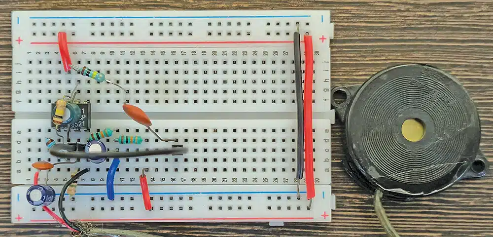
The electronic pulse waveform monitor demonstrates low-frequency signal amplification, high-impedance matching, and analogue signal processing. Designed to operate from a low-voltage DC supply, the device captures small mechanical vibrations produced by the body and converts them into a high-gain, conditioned analogue voltage waveform. Unlike standard airborne acoustic microphones, its contact-based piezoelectric transducer detects direct body vibrations, allowing physiological pulses to be displayed in real time on a digital storage oscilloscope (DSO). Fig. 1 shows the prototype on a breadboard.
The JFET-input TL071 operational amplifier is used to provide high-gain, low-noise amplification of the faint, low-frequency signals generated by the piezo sensor. A high-value resistor at the non-inverting input maintains the high input impedance needed to capture the weak sensor signal, while active and passive RC low-pass filters attenuate unwanted high-frequency noise. The circuit is assembled on a breadboard, with attention to supply decoupling, virtual-ground stability, and proper grounding to minimise mains interference.
Circuit and working
Fig. 2 shows the circuit diagram of the electronic pulse waveform monitor. It is built around a JFET-input operational amplifier TL071 (IC1), along with passive components for biasing, amplification, filtering, and signal conditioning. A 9V DC battery (BT1) provides a stable power supply, reducing interference from AC mains. Since the TL071 operates from a single-ended 9V supply, a 4.5V virtual-ground reference is created using two equal-value resistors, R1 and R2 (10kΩ each). Capacitor C2 (10µF) stabilises this reference against voltage fluctuations.
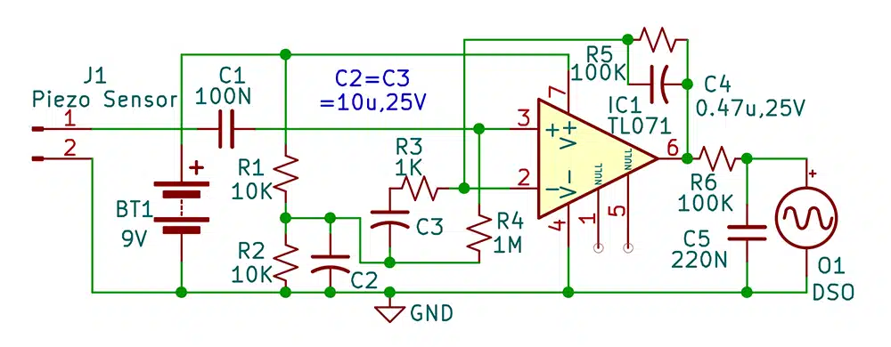
The piezo sensor is connected across connector J1, with its signal coupled through C1 (100nF) to the non-inverting input pin 3 of IC1. Resistor R4 (1MΩ) connects this input to the 4.5V virtual ground, providing the required DC bias while maintaining a high input impedance. This allows the circuit to detect the small, low-frequency electrical signals generated by the piezo element without significantly loading or attenuating them.
TL071 is configured as a frequency-selective non-inverting amplifier. Resistors R5 (100kΩ) and R3 (1kΩ) set the AC voltage gain to approximately 101. Capacitor C3 (10µF) is connected in series with R3 to prevent the 4.5V DC bias from being amplified, keeping the DC gain close to unity. Capacitor C4 (0.47µF), connected in parallel with R5, provides high-frequency roll-off.
The amplified signal from pin 6 of IC1 is then passed through a secondary passive RC low-pass filter formed by R6 (100kΩ) and C5 (220nF). This stage further attenuates high-frequency noise and smooths the pulse waveform before it is observed on the digital storage oscilloscope (O1, DSO). The DSO therefore displays the conditioned pulse signal in real time for visual analysis.
Construction and testing
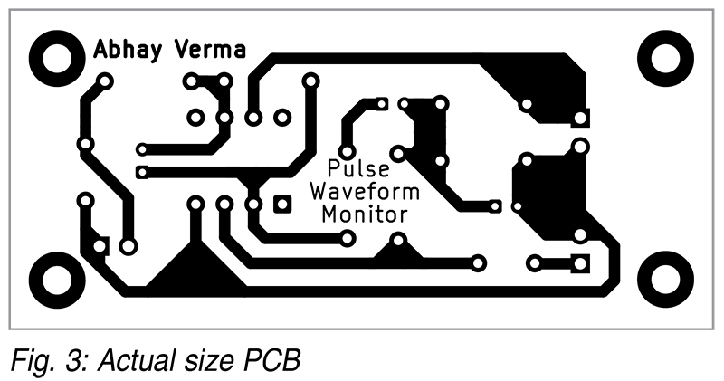
The actual-size single-sided PCB layout of the electronic pulse waveform monitor is shown in Fig. 3, and its component layout is shown in Fig. 4. If a designed PCB is unavailable, the circuit can be assembled on a general-purpose PCB or on a breadboard.
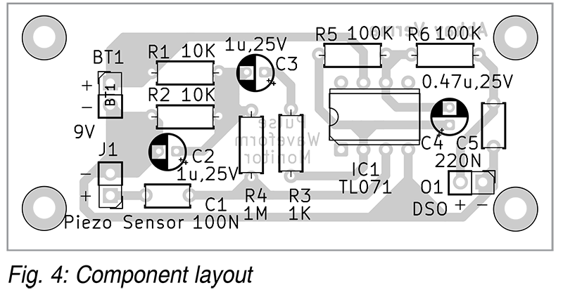
Since the circuit handles low-level analogue signals, keep the wires between the piezo sensor and breadboard as short as possible. Alternatively, use a shielded audio cable to minimise external noise. Connect the battery negative terminal, DSO ground clip, and all circuit ground connections to a single point on the breadboard ground rail to minimise ground-loop noise. Also, ensure that electrolytic capacitors C2 and C3 are connected with the correct polarity for stable operation of the circuit. The piezo transducer should be securely mounted in a small rigid enclosure to prevent movement, accidental finger contact, and unwanted electrical noise.
Securing the piezo sensor for measuring pulse
Use a piezo sensor/disc at connector J1. Place the sensor gently on the inside of the wrist over the radial artery, where the pulse can be felt. Secure it lightly with medical tape or a small elastic band so that it remains stationary, but do not press it tightly, as excessive pressure can reduce the pulse signal. The sensor can also be positioned gently over another suitable pulse point, such as the carotid artery. Connect the sensor to J1 as shown in the circuit.
The mechanical pressure variations produced by each heartbeat cause the piezo element to flex slightly, generating a small electrical signal. This signal is coupled through C1 to the TL071 operational amplifier, which amplifies it and produces the pulse waveform at the output.
| Parts List |
| Semiconductor: IC1 – TL071 op-amp IC Resistors (all 1/4-watt, ±5% carbon): R1, R2 – 10kΩ R3 – 1kΩ R4 – 1MΩ R5, R6 – 100kΩ Capacitors: C1 – 100nF ceramic disc C2, C3 – 10µF, 25V electrolytic C4 – 0.47µF, 25V electrolytic C5 – 220nF ceramic disc Miscellaneous: BT1 – 9V battery J1 – Piezoelectric sensor O1 – Digital storage oscilloscope – General-purpose PCB/breadboard – Connecting/jumper wires |
Testing the circuit
After assembling the circuit, connect a 9V battery as the power source. To observe the signal, connect the ground clip of a digital storage oscilloscope (DSO) to the common ground rail of the breadboard and connect the active probe to the output of the final passive filter stage, at the junction of R6 and C5. Initially, set the DSO to AC coupling, a slow horizontal timebase of about 200ms/division-500ms/division, and a vertical sensitivity of approximately 500mV/division.
Before testing the pulse signal, lightly tap or gently press the piezo sensor with a finger to verify that the circuit responds to mechanical vibrations. A corresponding waveform should appear on the DSO screen.
Next, place the sensor gently over the radial artery at the wrist and keep the hand relaxed and still. The small pressure variations caused by each heartbeat flex the piezo element and generate a rhythmic electrical signal.
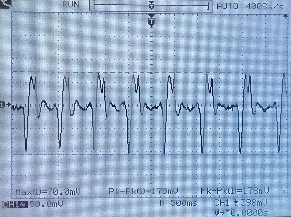
If the circuit is functioning correctly, a continuous pulse waveform should be visible on the DSO, as shown in Fig. 5. If no waveform is observed, check the 9V supply, ground connections, J1 wiring, capacitor polarity, and the TL071 output and filter connections.
Learning points
The device demonstrates how basic electronic components can be combined to monitor the human pulse. Tiny physical vibrations produced by the heartbeat are detected by the piezo sensor and converted into electrical signals. These weak signals are then amplified and shaped into a clear pulse waveform by the operational amplifier.
Capacitors in the signal path and filter stages suppress unwanted high-frequency noise and improve the quality of the output waveform. Proper wiring and grounding further minimise common sources of interference, such as 50Hz/60Hz mains hum and static noise caused by handling.
Abhay Verma is an electronics engineer at EFY and a passionate electronics hobbyist with a keen interest in practical circuit design and DIY projects.