
For industrial prototyping and design, we often need industrial-grade sensors and devices plus industrial platforms like EdgeX. But interfacing and using those industrial-grade sensors with our known boards is very difficult and unknown to us. So here we use the industrial platform EdgeX and industrial sensors and interface them with the known Raspberry Pi for edge computing.
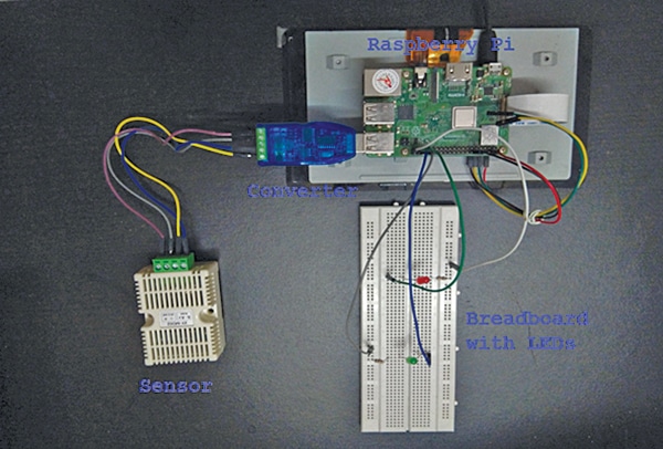
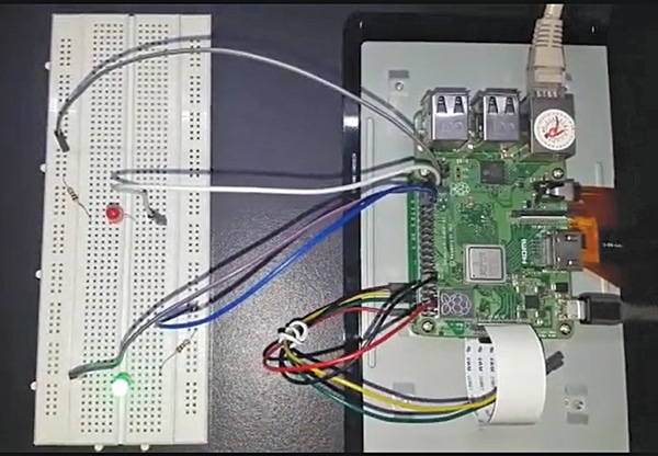
Here we read the temperature and humidity values of the SHT20 sensor and leverage the EdgeX framework running on Raspberry Pi to provide gateway functionality. Using EdgeX framework microservices, we process the sensor data and send it to the cloud. After that, we actuate LEDs to on/off when temperature readings cross threshold values. The author’s prototype is shown in Fig. 1.
POC Video Tutorial In English:
POC Video Tutorial In Hindi:
EdgeX framework speeds time to market by providing replaceable reference services for device-data ingestion, normalization, edge intelligence, and sharing to support new IoT data services and advanced edge computing applications. The scope of this case study is to leverage and exercise the functionality of the EdgeX framework and demonstrate monitoring temperature and humidity sensors. Industrial-grade temperature and humidity transmitter SHT20 is used for the case study.

| Bill of Material | |
| Component | Quantity |
| Raspberry Pi 4 | 1 |
| SD card | 1 |
| LED | 1 |
| Temperature and humidity transmitter Modbus SHT20 Sensor XY-MD02 | 1 |
| 5V, 2A DC power adaptor | 1 |
| Breadboard | 1 |
| 5V DC industrial CH340 USB to RS485 converter communication module | 1 |
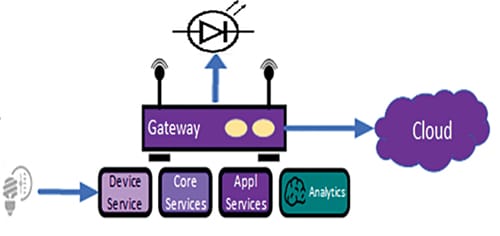
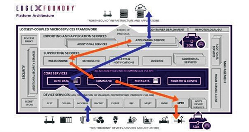
A typical block diagram using EdgeX in Fig. 2 shows the high-level block diagram for edge computing using EdgeX. It is taken from the image source.
Let’s Setup the System…
For using EdgeX and industrial temperature sensor we need the Ubuntu operating system (OS) for Raspberry Pi 4. The latest Ubuntu OS can be downloaded from the link and the SD card can be prepared by following the steps given therein.

Ubuntu Installation
After preparing the SD card with Ubuntu OS make the following changes before booting Raspberry Pi using the micro SD card in which Ubuntu has been installed:
- To enable USB ports for the keyboard, add the following line in /boot/config.txt file:
max_usb_current=1
- To enable HDMI ports for display, add the following lines in /boot/config.txt file:
hdmi_force_hotplug=1

hdmi_drive=2 - To enable SSH, touch the file “ssh” in /boot directory.
After the above changes, you can boot the Raspberry Pi by connecting it to 5V DC power adaptor and your TV or monitor using HDMI and providing internet connectivity using LAN, Wi-Fi, or USB tethering through a mobile phone. Then login with the default credentials (ubuntu/ubuntu) and update the password and get the IP address assigned using command “sudo ip addr”. Once you get internet access, you can SSH to Raspberry Pi from another device for remote access.
Next, you need to install EdgeX on the OS.
There are multiple ways to install EdgeX on Ubuntu. Check the detailed steps for the installation.
Snap way of installing EdgeX micro services is easy, but it is a read-only file. So, if there is an issue in debugging any of the microservices, say EdgeX device service, it won’t help as you cannot modify the configuration to debug or modify the code. To overcome the read-only problem of Snap and to debug the code, you can pull the code from GitHub, then build and run.
Sensor Device Validation
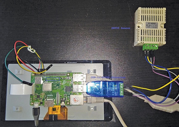
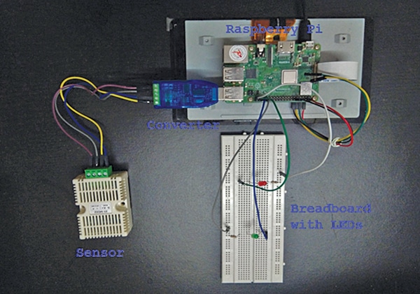
Sensor used for this case study is industrial-grade temperature and humidity transmitter SHT20 sensor high precision monitoring Modbus RS485. Sensor SHT20 sends temperature and humidity values with a multiple of 10. After receiving the values, you need to divide them by 10 to get the correct readings. Industrial USB-to-RS485 bidirectional half duplex serial line converter is used for sending and receiving values from the sensor. Jumper wires are used to connect the sensor to converter. Fig. 3 shows connection of SHT20 sensor to Raspberry Pi using USB-to-RS485 converter.
Reading Values
Our objective is to check the functionality of the sensor without using EdgeX, so that we can validate whether the sensor is working as expected or not. The author tested the Modbus messages from sensor with a C program. In C program, libmodbus library is used, which provides the APIs to send and receive messages in Modbus protocol.
——————————————–
root@ubuntu:/home/ubuntu/test# gcc -o readVaules read_sensor_values.c `pkg-config –cflags –libs libmodbus`
root@ubuntu:/home/ubuntu/test# ./readVaules
Setting slave_id 1
Opening /dev/ttyUSB0 at 9600 bauds (N, 8, 1)
[01][04][00][01][00][02][20][0B]
Waiting for a confirmation…
<01><04><04><01> <4A><02><19><1B><04>
Temperature = 33.000000 & Humidity = 53.700000
root@ubuntu:/home/ubuntu/test#
——————————————–
Decoding Modbus Messages
Let’s decode a pair of messages sent to and received from the sensor. Request sent to the sensor: 01 04 00 01 00 02 20 0B
| Sent | Decoding |
| 1 | Slave ID |
| 4 | Function, read_input_registers |
| 00 01 | Register address |
| 00 02 | Number of registers to read |
| 20 0B | CRC |
Response received from the sensor: 01 04 04 01 4A 02 1A 5B 05
| Received | Decoding |
| 1 | Slave ID |
| 4 | Function, read_input_registers |
| 4 | Bytes count |
| 01 4A | Data 1, Temperature |
| 02 1A | Data 2, Humidity |
| 5B 05 | CRC |
Temperature value received is 0x014a, which is 330 in decimal. SHT20 sends the values in multiple of 10, so temperature is 33.0 degrees. Similarly, Humidity value received is 0x021a, which is 538 in decimal. SHT20 sends the values in multiple of 10, so humidity is 53.8% RH.
Verifying LED Connectivity
To check the needed functionality of breadboard connections with LEDs, a breadboard, an LED, resistors, and jumper wires are required.
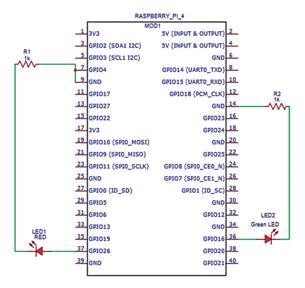
Like Modbus connectivity verification, here too the objective is to verify the breadboard and LEDs connectivity without using EdgeX in first place. The logical diagram in Fig. 4 shows connection of GPIO pins of Raspberry Pi with LEDs present on breadboard using https://www.circuit-diagram.org/editor/
The circuit diagram provides a convenient way of depicting the connections.
The author has tested the LEDs functionality with a Python program. Package RPi.GPIO provides a class to control the GPIO on a Raspberry Pi. Breadboard actual connections and output of green LED glow is depicted in Fig. 4, which shows circuit connections of GPIO pins to LEDs on breadboard, while Fig. 5 shows the actual connections of GPIO pins to LEDs on breadboard.
End-to-end Data Flow
The objective of this case study is to use EdgeX framework to read the data from the sensor and send it to cloud to actuate LEDs whenever the temperature reaches upper or lower threshold values. Raspberry Pi is the IIoT gateway. Corresponding physical connections for the end-to-end data flow are shown in Fig. 6.
Micro-services within EdgeX
Data flow indicated with blue arrows in Fig. 7 is from southbound to northbound, that is, from the sensor to cloud. Data flow indicated with orange arrows is from northbound to southbound, that is, from the application service to LED actuation.
For the data flow from southbound to northbound (sensor to cloud):
- Modbus device service retrieves the temperature and humidity values from the sensor using Modbus messages every 5 seconds. Pulling data every 5 seconds is done using Auto Events in Modbus device service.
- Modbus device service applies scale factor of 0.1 before sending the sensor data to core services.
- Sensor data is stored temporarily in core services and received at application service based on the configuration within application service.
- Sensor data values can be fetched and verified using core command REST APIs.
- Application service will forward sensor values to the cloud configured in the configuration.toml file.
- You can monitor the sensor values using the IBM Cloud Portal.
For the data flow from northbound to southbound (application service to LED actuation): - Application service sends the sensor data to rules engine based on the configuration. Kuiper is the rules engine.
- The required rules should be added to the rules engine prior to receiving the sensor data from application service, so that it can actuate using the core commands of the GPIO device service mentioned in the rules.
- LEDs that must go on/off are already configured in GPIO device service. For this case study, pin GPIO-12 is configured with red LED and pin GPIO-14 is configured with blue LED. Core commands of GPIO-12 and GPIO-14 are added with corresponding rules in Kuiper.
- Threshold values for case study are, blue LED must glow if the temperature goes below 28 degrees and red LED must glow if the temperature goes above 30 degrees. Between 28 degrees and 30 degrees both the LEDs should be off.
- Sensor data received from application service is analyzed by Kuiper and, as per the configured rules, core commands of GPIO device service are actuated when threshold values are reached.
- Based on the commands triggered by Kuiper, the GPIO device service actuates the corresponding LEDs on or off.
Analyzing the Data Flow
The following section analyses the data flow at various stages when sent from southbound to northbound and vice versa.
Modbus device service. It retrieves the temperature and humidity values from the sensor using Modbus messages every 5 seconds. Modbus logs from the case study are:
——————————————–
2021/03/02 14:35:21 modbus: sending 01 04 00 01 00 01 60 0a
2021/03/02 14:35:21 modbus: received 01 04 02 01 50 b8 9c
——————————————–
The messages sent to and received from the sensor are decoded as shown below:
| Sent | Decoding |
| 1 | Slave ID |
| 4 | Function, read_input_registers |
| 00 01 | Register address |
| 00 01 | No. of registers to read |
| 60 0a | CRC |
Temperature value received is 0x0150, which is 336 in decimal. SHT20 sends the values in multiple of 10, so temperature is 33.6 degrees.
| Received | Decoding |
| 1 | Slave ID |
| 4 | Function, read_input_registers |
| 2 | Bytes count |
| 01 50 | Data, temperature |
| b8 9c | CRC |
Core and Application Services
Sensor data values captured at core service using REST APIs of core command are shown in Fig. 8.

Application service will send the data to IBM Cloud, which is configured in the configuration.toml file. Application service logs when data is sent to the cloud are:
——————————————–
level=DEBUG ts=2021-03-21T14:35:48.355521757Z app=AppService- source=runtime.go:59 msg=”Processing message: 5 Transforms”
level=DEBUG ts=2021-03-21T14:35:48.36118818Z app=AppService- source=filter.go:44 msg=”Filtering by DeviceID”
level=DEBUG ts=2021-03-21T14:35:48.364375438Z app= AppService- source=filter.go:86 msg=”Filtering by ValueDescriptor”
level=DEBUG ts=2021-03-21T14:35:48.367788325Z app= AppService- source=conversion.go:62 msg=”Transforming to JSON”
level=DEBUG ts=2021-03-21T14:35:48.371520359Z app= AppService- source=mqtt.go:138 msg=”Sent data to MQTT Broker”
level=DEBUG ts=2021-03-21T14:35:48.37480595Z app= AppService- source=context.go:80 msg=”Marking event as pushed”
——————————————–
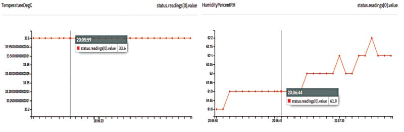
Snapshots of sensor data from the IBM Cloud portal are shown in Fig. 9.
Rules Engine
Another application service sends the data to rules engine Kuiper, which actuates the LEDs by triggering the corresponding GPIO core commands when configured temperature thresholds are crossed. Kuiper receives the sensor data sent by the application service and applies the rules which are preconfigured for actuation.
For the case study, following are the steps required to configure rules in Kuiper:
——————————————–
bin/kuiper drop stream edgex_data
bin/kuiper create stream edgex_data”() WITH(FORMAT=\”JSON\”, TYPE=\”edgex\”)”
bin/kuiper create rule red_led_on -f rule1.txt
bin/kuiper create rule red_led_off -f rule2.txt
bin/kuiper create rule blue_led_off -f rule3.txt
bin/kuiper create rule blue_led_on -f rule4.txt
——————————————–
From the above, rule1.txt actuates red LED on when temperature value goes beyond 30 degrees, and rule2.txt actuates red LED off when temperature drops below 30 degrees. Similarly, rule3.txt actuates blue LED off when temperature goes beyond 28 degrees, and rule4.txt actuates blue LED on when temperature drops below 28 degrees. Logs when red LED is actuated are:
——————————————–
root@ubuntu:/home/ubuntu/new_testing/kuiper/kuiper/_build/kuiper-1.1.1-4-g24892eb-linux-aarch64# tail -f ./log/stream.log
time=”2021-03-02 14:35:21” level=info msg=”sink result for rule blue_led_off: [{\”TemperatureDegC\”:33.6}]” file=”sinks/log_sink.go:16” rule=blue_led_off
time=”2021-03-02 14:35:21” level=info msg=”sink result for rule red_led_on: [{\”TemperatureDegC\”:33.6}]” file=”sinks/log_sink.go:16” rule=red_led_on
——————————————–
Instead of LED actuation, necessary actions can be taken for industrial use cases through relays and solenoids.
GPIO Device Service
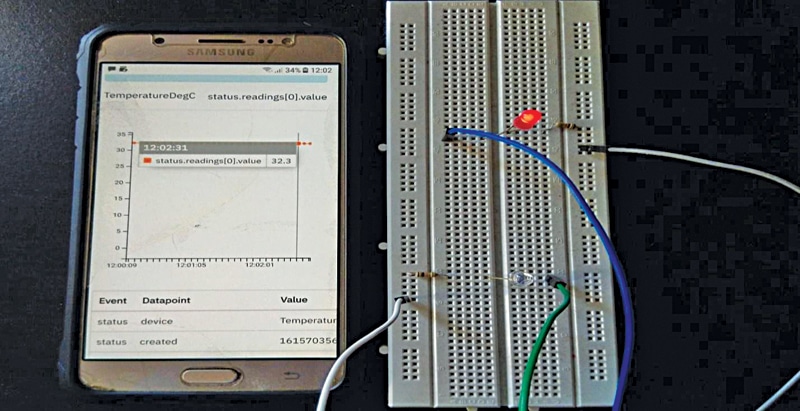
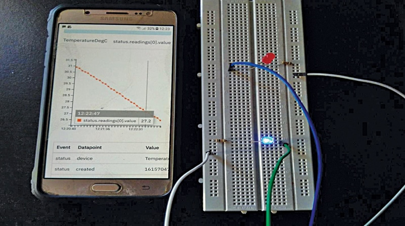
GPIO device service switches the LEDs on/off when core command of the corresponding GPIO pin is triggered by Kuiper. A snapshot of the red LED actuation along with live values in IBM Cloud portal are shown in Fig. 10. Fig. 11 shows a snapshot of the blue LED’s actuation with corresponding values.
Download Source code
Vijay Kumar Gopu, working as a technical specialist with HCL Technologies, has working experience in the areas of Virtualisation and Wireless Core Networks