


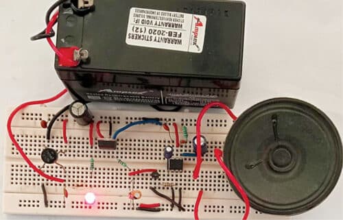
 This simple musical horn can be used in a car, scooter, cycle, or motorbike, or even as a call-bell. It uses melody generator IC UM66 that generates a musical tone, which is amplified by IC LM386. The tone of the horn cannot, however, be changed as no potentiometer has been used to keep the circuit simple. The author’s prototype is shown in Fig. 1.
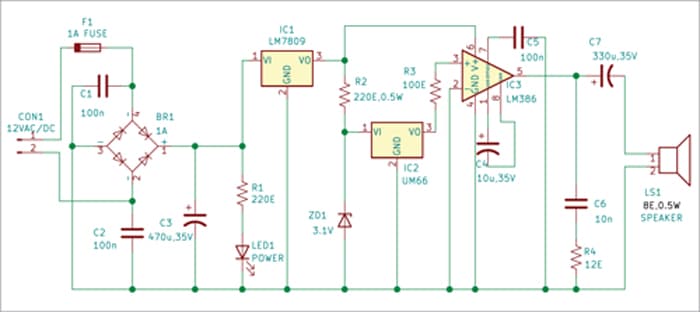
Circuit diagram of the musical horn is shown in Fig. 2. The circuit comprises a bridge rectifier (BR1), 9V voltage regulator 7809 (IC1), melody generator UM66 (IC2), low-power audio amplifier LM386 (IC3), and a few other components. Capacitors connected across the supply terminals are used to minimize any noise signals.
Video Tutorial:

Heart of the circuit is melody generator IC UM66. The IC has an inbuilt beat and tone generator. It has three legs like a transistor and is available in many versions that produce different melodies. The UM66 series of ICs is meant for use in call bells, cell phones, and toys.
IC UM66 has a built-in ROM program for music and consumes very low power. The melody signal is generated at pin 3 of UM66 and it is amplified by LM386 to drive the loudspeaker. The circuit can generate music even without audio amplifier LM386, but the volume will be very low.
The UM66TXX series is designed specifically to generate melody for tone generation circuits. Last two digits of the IC specify the tone/melody generated by that IC. The list of some common tone generator ICs and their equivalent numbers are:
UM66T01 – Jingle bells, Santa is coming to town, and We wish you a merry Xmas
UM66T02 – Jingle bells
UM66T04 – Jingle bells, Rudolph the red-nosed reindeer, and Joy to the world
UM66T05 – Home sweet home (a nice melody)
UM66T06 – Let me call you Sweetheart
UM66T08 – Happy Birthday to you
The UM66 melody tone generator IC used in the circuit may be changed to any other in the series to change the melody.
This musical horn circuit can work on 12V DC as well as 12V AC. If you want to operate it on AC mains, use a 230V AC primary to 12V, 500mA secondary transformer to step down the AC mains voltage to 12V AC. The stepped-down AC voltage may be connected directly across CON1 in the circuit.
The 12V AC voltage is rectified using bridge rectifier BR1 and filtered by capacitors C1 and C2 to remove any ripples in the voltage. The rectified and filtered voltage is then regulated to 9V by regulator IC 7809. In case you want to use 12V DC, connect it directly across CON1.
The LM386 is a power amplifier designed for use in low-voltage consumer applications. Its gain is internally set to 20, but the addition of an external resistor and capacitor between pins 1 and 8 will increase the gain to any value up to 200. The amplifier’s inputs are ground referenced while the output automatically biases to one-half the supply voltage.
| Parts List |
|
Semiconductors:
IC1 – 7809, 9V voltage regulator IC2 – UM66 melody generator IC3 – LM386 low-power audio amplifier BR1 – 1A bridge rectifier ZD1 – 3.1V, 0.5watt Zener diode LED1 – 5mm LED Resistors (all 1/4-watt, ±5% carbon), unless stated otherwise: R1 – 220-ohm R2 – 220-ohm, 0.5-watt R3 – 100-ohm R4 – 12-ohm Capacitors: C1, C2, C5 – 100nF ceramic disk C3 – 470µF, 35V electrolytic C4 – 10µF, 35V electrolytic C6 – 10nF ceramic disk C7 – 330µF, 35V electrolytic Miscellaneous: CON1 – 2-pin connector LS1 – 8-ohm, 0.5-watt loudspeaker BATT.1 – 12V battery (or 12V AC) F1 – 1A fuse with holder |
The operating voltage of the circuit is 12V AC or DC. The UM66 works between 1.5V and 4.5V DC, so a Zener diode has been used here for providing 3.1V to UM66. Power amplifier LM386 works on 4V to 18V; here it uses 9V generated by IC 7809 for a sufficiently loud sound.
The output of IC UM66 is given to input of LM386 for amplification of the melody generated by UM66. The LM386 has a 10µF capacitor connected between its pins 1 and 8, which is used for the gain of the amplifier. A push button/momentary switch (not shown in circuit diagram) is used to turn on the circuit, thereby producing a loud horn sound.
Working of the circuit is simple. After connecting 12V AC/DC across CON1, the circuit is ready for use. As soon as power is switched on, LED1 glows and at the same time the speaker produces a musical sound.
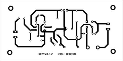
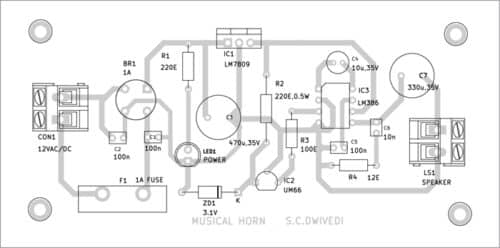
An actual-size, single-side PCB layout for the musical horn is shown in Fig. 3 and its component layout in Fig. 4. After assembling the circuit on PCB, enclose it in a suitable box. Fix LED1 in front of box and the speaker on the rear side. The circuit is now ready for use.
Bonus. You can watch the video of the tutorial of this DIY project at: Link
S.C. Dwivedi is an electronics enthusiast and circuit designer at EFY