Here’s a simple circuit of an electronic horn that is built around quadruple op-amp IC LM3900 (IC1). IC LM3900 has four independent op-amps (A1 through A4) with a large output voltage swing. It can work at up to 32V DC.
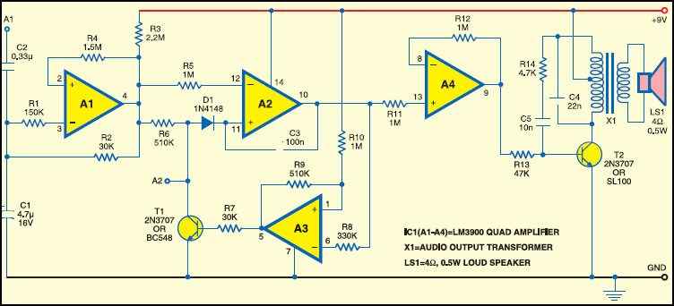
The first op-amp (A1) is wired as a low-frequency squarewave generator. Op-amp A2 works as an integrator, while op-amp A3 works as a comparator. A2 and A3 together work as a ‘wandering voltage generator’ op-amp. Op-amp A4 is wired as a buffer and its output provides base current to npn transistor T2. npn transistor T2 and audio output transformer X1 form a voltage-controlled oscillator.
When power is switched on, a basic tone is generated by transistor T2 and transformer X1, which is frequency-modulated by the wandering voltage generator, which, in turn, is influenced by the low-frequency squarewave generator. The circuit works off regulated 9V. To generate several different tones, connect its point A1 to pins 1, 3, 4, 5, 8, 9, 10, 11, 12 and 13 of IC1 and point A2 to pins 1, 2, 3, 6, 8, 11 and 13.

The circuit can be used as an automobile horn by using about 10W audio amplifier.