


 This LED based message display is built around readily available, low cost components. It is easy to fabricate and makes use of 3mm red LEDs. A total of 172 LEDs have been arranged to display the message “HAPPY NEW YEAR 2004.”
LED based message display circuit
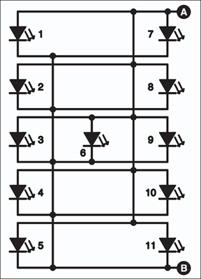
The arrangement of LED1 through LED11 is used to display ‘H’ as shown in Fig. 1. The anodes of LED1 through LED11 are connected to point A and the cathodes of these LEDs are connected to point B. Similarly, letter ‘A’ is built using LED12 through LED21. All the anodes of LED12 through LED21 are connected to point A, while the cathodes of these LEDs are connected to resistor R8 (not shown in the circuit diagram). Other letters/words can also be easily arranged to make the required sentence.
The power supply for the message display circuit (Fig. 2) comprises a 0-9V, 2A step-down transformer (X1), bridge rectifier comprising diodes D1 through D4, and a filter capacitor (C1). IC 7806 (IC1) provides regulated 6V DC to the display circuit comprising timer 555 (IC2) and decade counter CD4017 (IC3). The astable multivibrator built around IC2 produces 1Hz clock at its output pin 3. This output is connected to clock pin (pin 14) of the decade counter.

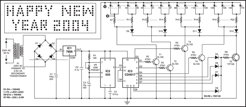
The decade counter can count up to 10. The output of IC3 advances by one count every second (depending on the time period of astable multivibrator IC2).
Circuit operation
When Q1 output of IC3 goes high, transistor T1 conducts and the current flows through LED1 through LED48 via resistors R7 through R11. Now the word ‘HAPPY’ built around LED1 through LED48 is displayed on the LED arrangement board.
Next, when Q2 output of IC3 goes high, transistor T2 conducts and the current flows through LED49 through LED87 via resistors R12 through R14. Now the word ‘NEW’ is displayed on the LED arrangement board.
Again, when Q3 output goes high, transistor T3 conducts and the current flows through LED88 through LED128 via resistors R15 through R18. Now the word ‘YEAR’ is displayed on the LED arrangement board.
Similarly, when Q4 output goes high, transistor T4 conducts and the current flows through LED129 through LED172 via resistors R19 through R22. Now digits ‘2004’ are displayed on the LED arrangement board.
During the entire period when Q5, Q6, Q7, or Q8 output go high, transistor T5 conducts and the current flows through all the LEDs via diodes D9 through D12 and resistors R7 through R22. Now the complete message “HAPPY NEW YEAR 2004” is displayed on the LED arrangement for four seconds.
Thus, the display board displays ‘HAPPY,’ ‘NEW,’ YEAR’ and ‘2004’ one after another for one second each. After that, the message “HAPPY NEW YEAR 2004” is displayed for 4 seconds (because Q5 through Q8 are connected to resistor R6 via diodes D5 through D8).
At the next clock input output Q9 goes high, and IC3 is reset and the display is turned off for one second. Thereafter the cycle repeats.
Feel interested? Check out other electronics projects.
