


 Normally, digital speedometers are found only in luxury cars and high-end motorbikes. Even if your motorbike has a mechanical speedometer, what will you do when it gets damaged? First, you need to replace the mechanical worn gear and then the cable. Here we describe how to build a microcontroller based speedometer-cum-odometer for your motorbike. The circuit uses a microcontroller, an LCD display and some commonly available components. It is a better alternative to the mechanical speedometer and even a beginner with minimal skill level can assemble it.
The features of the digital microcontroller based speedometer-cum-odometer are:
1. Digital readout
2. Speed displayed in km/hour
3. Distance traveled displayed in kilometres
4. Readings saved in non-volatile memory (EEPROM)
5. Reliability due to use of the microcontroller
6. No mechanical wear and tear
7. Home-brewed speed transducer/sensor
8. Self reset to zero after completion of 99,999.9 km
9. Easy to build and fix onto the bike

Calculations
You first need to know the radius of the bike’s front wheel. The calculations here are based on Hero Honda’s Splendor model. The radius of the front wheel is 30 cm. (This can vary with the brand or model.)
Circumference of the wheel= 2πr (where ‘r’ is in cm)
= 2×3.14×30
= 188.4 cm or 1.884 metres

Speed: Let’s assume that in 1 second the wheel
completes one revolution. In other words, in one second, the bike has covered 1.88 metres. Therefore the speed in km/hour:
N×1.88×3600/1000
= N×6.784 or N×6.8
where ‘N’ is the number of revolutions per second.
‘6.8’ is a constant and only ‘N’ varies; for example, if ‘N’
is 5, the speed equals 5×6.8= 34 km/hour.
Distance: The odometer is updated every 100 metres.
To cover 100 metres, the wheel is required to make approximately 53 revolutions (100/1.88). The microcontroller takes care of the tasks of revolutions counting, speed calculation, conversion and display of results.
 Circuit description
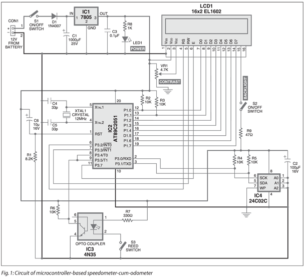
The circuit of the digital microcontroller based speedometer-cum-odometer is shown in Fig. 1. The functions of various components used in the circuit are described below.
Microcontroller
A 20-pin AT89C2051 microcontroller from Atmel is used here because of its low pin count, affordability and compatibility with CISC-based 8051 family. All the available pins of the microcontroller are utilised in the project. This microcontroller features 2 kB of Flash, 128 bytes of RAM, 15 input/output (I/O) lines, two 16-bit timers/counters, a five-vector two-level interrupt architecture, a full-duplex serial port, a precision analogue comparator, on-chip oscillator and clock circuitry.
LCD module
To display the speed and distance traveled, we have used a 16×2 alphanumeric
LCD based on HD44780 controller. The backlight feature of the LCD allows data to be visible even at night.
Serial EEPROM
The readings of the distance traveled are saved in an external serial EEPROM. Here, a 24C02 serial EEPROM based on Philips I2C protocol is used.
I2C bus protocol
The I2C bus consists of two active wires and a ground connection. The active wires, serial data line (SDA) and serial clock line (SCL) are bidirectional.
Every device hooked up to the bus has its own unique address, no matter whether it is an MCU, LCD driver, memory or ASIC. Each of these chips can act as a receiver and/or transmitter, depending on the functionality.Obviously, an LCD driver is only a receiver, while a memory or I/O chip can be both transmitter and receiver.
The I2C bus is a multi-master bus. This means that more than one IC capable of initiating a data transfer can be connected to it. The I2C protocol specification states that the IC that initiates a data transfer on the bus is considered the bus master. Bus masters are generally microcontrollers. Consequently, all the other ICs are regarded as bus slaves at that instant.
Circuit operation
Let’s assume that the MCU wants to send data to one of its slaves. First, the MCU will issue a START condition. This acts as an ‘attention’ signal to all of the connected devices. All ICs on the bus will listen to the bus for incoming data. Then the MCU sends the address of the device it wants to access, along with an indication whether the access is a ‘read’ or ‘write’ operation. Having received the address, all ICs will compare it with their own ad-dress. If it doesn’t match, they simply wait until the bus is released by the stop condition. If the address matches, the chip will produce a response called ‘acknowledge’ signal. We have used write operation in this project.
Once the MCU receives the acknowledge signal, it can start transmitting or receiving data. In our case, the MCU will transmit data. When all is done, the MCU will issue the stop condition. This signals that the bus has been released and that the connected ICs may expect another transmission to start any moment.
We have several states on the bus: start, address, acknowledge, data and stop. These are all unique conditions on the bus. In our project, the microcontroller is the master and the serial EEPROM is the slave.
The readings are periodically stored in the EEPROM and the previous reading is retrieved from the EEPROM each time the bike is started.
Speed sensor
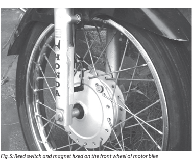
For this project, we make use of a simple homemade speed transducer. The rotation of the wheel is sensed by the combined action of a reed switch and a magnet fixed on the wheel. The sensor sends a pulse to the microcontroller each time a revolution is made.
Optocoupler
An optocoupler is used to counter the effects of bouncing when the contact of reed switch is closed.
Power supply
The power supply for various parts of the circuit is drawn from the vehicle’s 12V battery after reducing it to 5V using a three-terminal voltage.
Software
The ‘Init_EEPROM’ and ‘Speedo’ source codes of this project are written in Assembly language. These are compiled using an open-source ASEM-51 assembler to generate the Init_EEPROM.hex and Speedo.hex files. The hex files are burnt into the microcontroller chip.
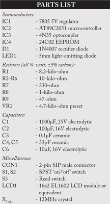
Two internal timers of the microcontroller are configured as 8-bit counters to count the number of pulses generated by the speed sensor. One timer is used to measure the distance and the other for speed calculation.
A software delay of one second is generated after the speed counter is triggered. The speed count value is obtained from the counter registers. To speed up the process, a look-up data table is stored in the ROM that helps the microcontroller to convert the number of pulses into the corresponding speed values. The program flow-chart is shown in Fig. 2.
The ‘distance’ counter is incremented every 100 metres. The wheel has to make 53 revolutions to achieve this. The distance counter is loaded with an initial value of 203 (255-53+1) and is incremented on each revolution. After 53 counts, the timer overflows and generates an interrupt to notify the microcontroller that 100 metres are covered.
In the interrupt service routine, the microcontroller updates the corresponding ‘DS1’ distance variable. Instead of saving distance variables after each cycle, the microcontroller saves these readings when the vehicle is athalt (speed is 00.0 km/hour). In other words, when the vehicle is stopped at traffic signals or before the ignition key is turned off, the last reading is saved to the EEPROM. The same reading is again retrieved from the EEPROM when the bike is turned on next time and the readings are updated for each trip.
Construction

The reed switch and a magnet need to be fixed on the front wheel of the motor bike (Hero Honda’s Splendor). A small circular magnet (about 2 cm in diameter), normally used in speakers of small toys, can be used. Fix the magnet to the central drum of the wheel just below the spokes connected to the drum. Secure the magnet using hot glue or Araldite.
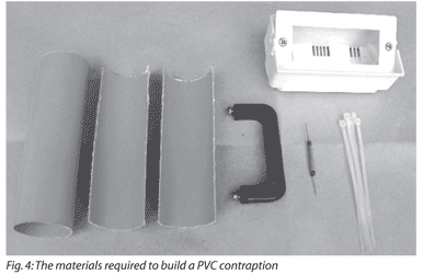
For fixing the reed switch, a PVC pipe contraption needs to be made so that the magnet and reed switch are aligned as shown in Fig. 3. The materials required to build the contraption are shown in Fig. 4. Cut a 3.2cm diameter PVC pipe measuring 15.2 cm in length perpendicularly into two halves. Use only one half of the PVC pipe. Mount and secure the reed switch using Araldite and cable ties on the plastic handle (normally used in emergency lights). Once it dries up, solder two wires to the two opposite end leads of the reed switch. Fix the plastic handle on the half cut PVC pipe using screws. Now, place the pipe on the front shock-absorber fork such that reed switch faces towards the magnet.
Connect a multimeter, set in continuity mode, to the two wires coming from the reed switch. Rotate the wheel slowly and see whether the reed switch closes when the magnet passes across it. If it does, the multimeter will give a continuity beep. When the magnet moves away from the reed switch, the beep will stop, indicating that the reed switch is open. Make a few trials to find the optimal position for mounting and fixing the PVC pipe such that the reed switch works smoothly. Mark the location on the front shock-absorber fork.
Now you can fix the PVC pipe contraption to the shock-absorber fork using hot glue as shown in Fig. 5. Use liberal amount of hot glue to secure it to the pipe. Carefully route the two wires up to the bike’s handle bar using cable ties to secure the wire. This completes the sensor mounting part.
The main circuit and the LCD module can be housed in suitable plastic enclosures, which are readily available in electronic projects shops. These enclosures should have precut slot for easy mounting of the LCD panel. If such boxes are not available, you can use the plastic boxes of electronic chokes by suitably removing some portions for the LCD panel.
Power supply can be taken either directly from the bike’s 12V battery or tapped from the console which houses horn, headlight and indicator light switches. For this, you need to remove the switch console and identify positive wire and ground wire using a multimeter. When carrying out this step, remember to turn the ignition key to ‘on’ position. Solder a 60cm two-core wire to the positive and negative terminals inside the switch console. The advantage of taking supply from the switch console is that the ignition key controls the power supply to the main unit without having a separate on-off switch.
An actual-size, single-side PCB layout of the microcontroller based speedometer-cum-odometer is shown in Fig. 7 (View as PDF), and its component layout in Fig. 8 (View as PDF).
Download PCB and component layout PDFs (Fig. 7, 8) : click here
Testing
After all the components are soldered on the PCB, program the microcontroller with Init_EEPROM.hex file and place the microcontroller in a 20-pin IC base and switch on the circuit.
In the first line of the LCD, ‘INIT_EEPROM’ appears. After five seconds, ‘00000.0’ is displayed in the second line. This process erases any previous data and sets the initial readings in the EEPROM to zero. Now switch off the supply and program the microcontroller with ‘speedo.hex’ main file. After programming, place the microcontroller back in the circuit and switch on the supply. The LCD will show ‘Kms: 00000.0’ in the first line and ‘Speed- Kms/ Hr: 00.0’ in the second line. Now, the unit is ready to mount on your bike.
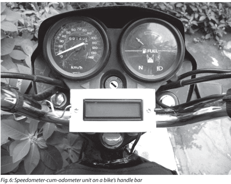
Connect the two wires coming from the reed switch and the power supply wires to the main unit. Mount the unit at the centre of the bike’s handle bar on top of the ‘U’ clamps that secure the handle bar to the chassis. You can use cable ties to accomplish this. Mounting arrangement of the unit is shown in Fig. 6.
Now start the bike, take a test ride and if connections are correct, the speed and the distance will be displayed on the LCD. A protective cover like polythene can be used for the main unit on rainy days.
Download source code: click here

need the code
The source code is present on the 3rd page of the article.
iam only getting the HEX files… can u please tell me the actual code
can i get this code in embedded c langauge
There are two hex files which one to burn on microcontroller ??
can i get the code in c
Where is c language programe
Speedometer coding neeed koi bi contact kr skta h 9711902972
the source code link is not working
The Source code is shared to your email id.