


Download PCB and Component Layout PDFs: Click here
Download Source Code: Click here
The TRIAC can be triggered by the current going into the gate. To create a triggering current, a positive or negative voltage has to be applied to the gate with respect to the MT1 terminal. Once triggered, the device continues to conduct until the current drops below a certain threshold called the holding current. When the gate current is discontinued, and if the current flowing between the two main terminals is more than what is called the latching current, the device keeps conducting.

After the TRIAC is turned on, removing the voltage at the gate will not turn the TRIAC to the off state. The only way the TRIAC can be turned off is by reducing the gate current below the holding current or reducing the current to zero by removing the voltage across MT1 and MT2.
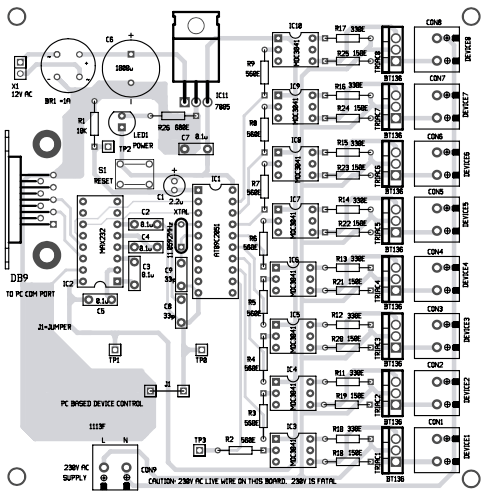
When sufficient current of the internal LED (MOC3041) is present, the TRIAC will re-trigger every half cycle of AC line voltage until the internal LED switches off and the power TRIAC has gone through a zero current point. The internal LED is turned on by the user from the PC, which in turn triggers the corresponding TRIAC, and the device connected across the TRIAC is switched on. Thus, each electrical device or appliance is controlled through a solidstate switch using a TRIAC and an opto-TRIAC.
Please share full source code..
Dear swanand, the source code is present on third page of the article.
can you please share vb code for the GUI application
You can download the complete source code including the VB code from here. http://www.efymag.com/admin/issuepdf/PC%20Based%20Electrical%20Equipment%20Control.rar
Hello sir,
How much time will it require to complete the whole working setup?
There is only Hex file available. Can you provide complete code of the micro controller?
where is the circuit diagram?
Dear Deepak Agarwal, the circuit diagram is present on the second page.
If you have to put a MicroController in the circuit to control 8 outputs from a PC, why not use Arduino? It can be interfaced with a PC with USB (Unlike this circuit which uses Serial port which is hard to find in PC today). No need to make circuit board because everything is on Arduino board.
Technology keeps on changing and so is serial com port. This article was published a few years back. But the fact is that you can find Serial Port in some Desktop PCs, server PCs, industrial PCs, etc. and if not PCI slots are available in them for adding Serial port cards.
hello sir,
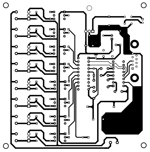
i noticed that in pcb layout device 1 and and remaing 2to 8 device connected in different manner with traic but in circuit diagram they all are conected in same way
i think devic 1con is not correctly conected in pcb layout plzz tell me the layout is correct or not
thanks reply asap.
Thanks for pointing out the mistake! There is a wrong track connecting to TRIAC1 and DEVICE1. It has been corrected now. The corrected actual-size PCB layout is available in PDF format for download. To download it, you can click ‘Click here’ hyperlink given just below the PCB layout in this article.
How can I get all setup Including PCBs