


In the equipment controller circuit, the devices are controlled through its port pins P1.0 through P1.7. The controlling is done by the user from the PC with the user interface shown in Fig. 7. The microcontroller is connected to the PC through MAX232 driver as shown in Fig. 2.
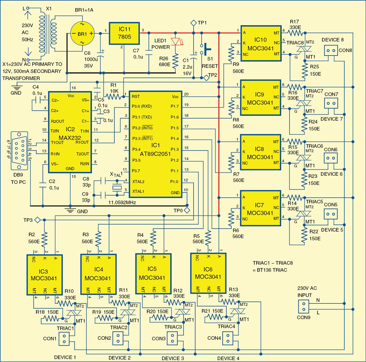
 MAX232. The serial output of the computer is connected to MAX232 driver IC2 through DB9 connector as shown in Fig. 2. The MAX232 IC is used for the long-distance and error-free transmission of data. It has two internal charge-pumps that convert +5V into ±10V for RS232 driver operation. Pins 11 and 12 of IC2 are connected to pins 3 and 2 of microcontroller IC1, respectively. serial data command from the PC is received by microcontroller IC1 through driver IC2. The microcontroller then triggers independent opto-TRIAC drivers for devices corresponding to the command received.
An RS232 serial port was once a standard feature of a personal computer, used for connections to modems, printers, mice, data storage, uninterruptible power supplies and other peripheral devices. Now, since it is becoming obsolete, one has to use an external USB-to-RS232 converter to connect to RS232 peripherals.

MOC3041. opto-TRIAC MOC3041 is a TRIAC driver, with inbuilt zero-crossing detector. The zero-crossing, optically-isolated TRIAC driver is an effective solution to interface the microcontroller ports with the AC power loads. A set of TRIAC driver and TRIAC is used for each load. When a particular load is switched on with the help of the personal computer, the particular TRIAC-driver of the corresponding device/load latches on. This action introduces gate current in the TRIAC (BT136).
BT136. TRIAC BT136 is a solidstate switch used for switching the electrical devices. It is a 3-pin device normally available in a TO220 plastic package. It has three terminals—MT1, MT2 and G (gate).

Please share full source code..
Dear swanand, the source code is present on third page of the article.
can you please share vb code for the GUI application
You can download the complete source code including the VB code from here. http://www.efymag.com/admin/issuepdf/PC%20Based%20Electrical%20Equipment%20Control.rar
Hello sir,
How much time will it require to complete the whole working setup?
There is only Hex file available. Can you provide complete code of the micro controller?
where is the circuit diagram?
Dear Deepak Agarwal, the circuit diagram is present on the second page.
If you have to put a MicroController in the circuit to control 8 outputs from a PC, why not use Arduino? It can be interfaced with a PC with USB (Unlike this circuit which uses Serial port which is hard to find in PC today). No need to make circuit board because everything is on Arduino board.
Technology keeps on changing and so is serial com port. This article was published a few years back. But the fact is that you can find Serial Port in some Desktop PCs, server PCs, industrial PCs, etc. and if not PCI slots are available in them for adding Serial port cards.
hello sir,
i noticed that in pcb layout device 1 and and remaing 2to 8 device connected in different manner with traic but in circuit diagram they all are conected in same way
i think devic 1con is not correctly conected in pcb layout plzz tell me the layout is correct or not
thanks reply asap.
Thanks for pointing out the mistake! There is a wrong track connecting to TRIAC1 and DEVICE1. It has been corrected now. The corrected actual-size PCB layout is available in PDF format for download. To download it, you can click ‘Click here’ hyperlink given just below the PCB layout in this article.
How can I get all setup Including PCBs