


Here is an easy-to-construct temperature indicator-cum-controller that can be interfaced with a heater’s coil to maintain the ambient room temperature. The temperature control system is based on Atmega8535 microcontroller, which makes it dynamic and faster, and uses an LCD module to display and two keys to increase or decrease the set values.
Temperature control system circuit
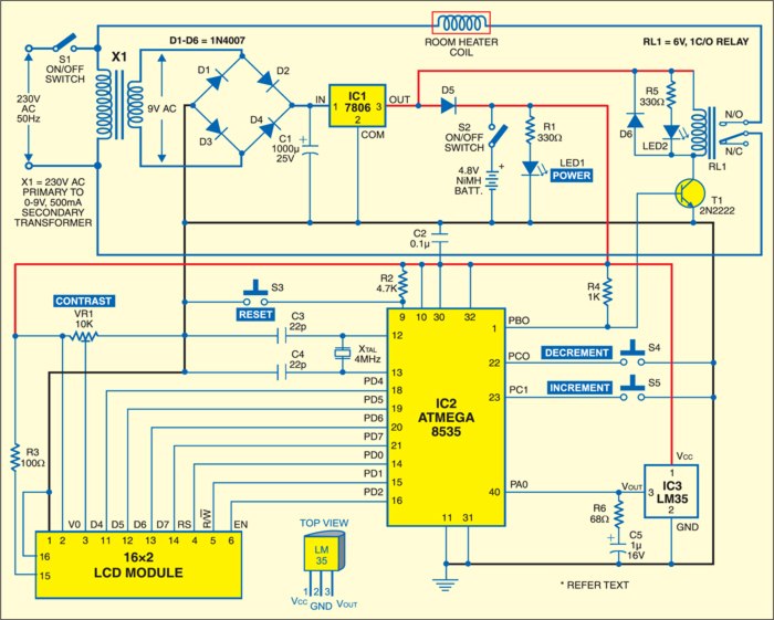
Fig. 1 shows the circuit of the temperature control system. It comprises microcontroller Atmega8535, temperature sensor LM35, regulator 7806, an LCD module and a few discrete components.
The 230V, 50Hz AC mains is stepped down by transformer X1 to deliver a secondary output of 9V, 500 mA. The transformer output is rectified by a full-wave bridge rectifier comprising diodes D1 through D4, filtered by capacitor C1 and regulated by IC 7806 (IC1). LED1 acts as the DC power indicator. Resistor R1 acts as the current limiter. A 4.8V rechargeable battery provides battery backup.

The ATmega8535 is a low-power CMOS 8-bit microcontroller based on the AVR enhanced RISC architecture. ATmega8535 has such features as 8 kB of in-system programmable flash memory (i.e., read-while-write capabilities), 512-byte EEPROM, 512-byte SRAM, 32 general-purpose input/output (I/O) lines, 32 general-purpose working registers, three flexible timers/counters with compare modes, internal and external interrupts, a serially programmable USART, a byte-oriented two-wire serial interface, an 8-channel, 10-bit analogue-to-digital converter (ADC) with optional differential input stage with programmable gain, a programmable watchdog timer with internal oscillator, an SPI serial port, and six software-selectable power-saving modes.
Download PCB and component layout PDFs: click here
The AVR core combines a rich instruction set with 32 general-purpose working registers. All 32 registers are directly connected to the arithmetic logic unit (ALU), allowing two independent registers to be accessed in one single instruction executed in one clock cycle. The resulting architecture is more code-efficient while achieving throughputs up to ten times faster than the conventional complex instruction set computer (CISC) microcontroller.

Port-A pin PA0 of the microcontroller is used as the ADC to interface the temperature sensor, which converts signals into digital equivalent. Capacitor C5 protects the ADC input from voltage fluctuations and resistor R6 is used as the current limiter.
Port D is used to interface the LCD module, which displays the set reference temperature value and the present temperature. Port-D pins PD0 through PD2 are connected to pins 4 through 6 (RS, R/W, EN), and pins PD4 through PD7 to D4 through D7 of the LCD module, respectively. Contrast is controlled by preset VR1. Resistor R3 limits the current of backlight of the LCD.
Port-C pins PC0 and PC1 are used to interface switches S4 and S5 for decrementing and incrementing the temperature setting as per the room temperature.
Port-B pin PB0 is used to control the relay with the help of transistor T1.
The room heater coil is connected to contacts of relay RL1. LED2 is connected in parallel with the relay to indicate the power-‘on’ status of the relay and the heater. D6 acts as a free-wheeling diode. A 4MHz crystal, connected between pins 12 and 13 of the microcontroller, provides the basic clock frequency for the microcontroller. Switch S3 is used for manual reset.
The temperature measured using LM35 is compared with the reference value. If the measured temperature is higher than the reference value by 1ºC, the heater is switched off, and if the measured temperature is lower than the reference value by 1ºC, the heater is switched on.
Whenever the temperature of the environment is lower than the reference temperature by 1ºC, pin PB0 goes high. Because of this, transistor T1 goes into saturation and the relay energizes. The heater connected with AC mains by the normally-open (N/O) contacts of the relay increases the temperature of surroundings. Similarly, when the temperature of surroundings is higher than the reference temperature by 1ºC, pin PB0 goes low, transistor T1 cuts off, the relay de-energises and heater is disconnected from mains. This results in lowering of the temperature to reference value. The circuit in this manner works as a temperature indicator-cum-controller.
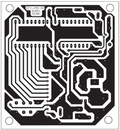
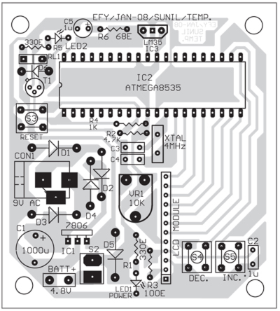
An actual-size, single-side PCB for the microcontroller-based temperature indicator-cum-controller is shown in Fig. 2 and its component layout in Fig. 3.
Software
The software is written in ‘C’ language and compiled using CodeVision AVR C compiler. The source program is converted into hex code by compiler. Burn this hex code into Atmega8535 AVR microcontroller. The source program is well commented and easy to understand.
First, declare that the microcontroller’s port D is used for communication with the LCD module and then include the header files like mega8535.h, lcd.h, delay.h and stdio.h. Thereafter, define the justified external reference voltage and then the subroutine for the microcontroller to read the digital equivalent input.
The lcd_init(16) function initialises the 16-x2-line LCD.
The lcd_clear( ) function clears the LCD and sets the displaying character position at row ‘0’ and column ‘0.’
The lcd_gotoxy(0, 0) function sets the current display position at column ‘0’ and row ‘0.’
The delay_ms(50) function generates a delay of 50 milliseconds.
The loop works to get temperature, read temperature, convert it into Celsius and then display on the LCD module.

need synopsis for this project!! Temperature cum indicator controller
sir pls send the program
The source code is present on the last page of the article.
what will be the cost for this project