


In today’s technologically advanced world, simplicity and security are top priorities. Password-based Home appliance control system is a cost-effective solution that combines both these aspects.
This project introduces a novel way to operate home appliances, such as lights or fans, using a secure password as the key.
In this article, we delve into the concept, circuitry, working principle, and potential applications of this innovative system.

But wait! There is something more…
Many times, mischievous folks, especially kids, enjoy ringing doorbells over and over again and then running away quickly. It’s quite annoying!
This happens because most doorbells have just one button, and they don’t have any security features.
But here’s the good news: the idea behind this circuit can do more than just control appliances. It can also work like a doorbell that needs a password, making homes safer.
| Components Required to Build Home Appliance Control System | |
| Semiconductors: | |
| IC1 (IC1A-IC1E) | -74LS32 quad 2- input OR gate |
| IC2 (IC2A-IC2E) | -74LS00 quad 2- input NAND gate |
| IC3 (IC3A-IC3G) | -74LS04 hex inverter (NOT gate) |
| IC4 (IC4A-IC4E) | -74LS02 quad 2- input NOR gate |
| IC5 | -ULN2003 relay driver |
| Miscellaneous: | |
| CON1-CON3 | -2-pin connector |
| RL1 | -5V one changeover relay |
| S1-S7 | -On/off switch |
| EA | -60W, 230V AC bulb |
The password-based home appliance control project is simple yet brilliant. It uses a secure password to turn On and Off electrical appliances.
The core components of this system include logic gates and a relay driver IC. They both team up to ensure the correct functioning of the setup.
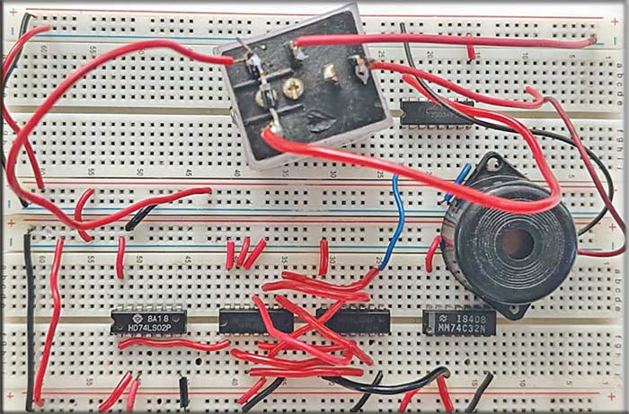
Fig. 1 shows the prototype tested in the EFY lab in which a buzzer was used as an appliance. We used jumper wires in place of switches.
Video Tutorials in English and Hindi are available at the end of the article.
Recommended: 25 Innovative Automation Projects
Home Appliance Control System – Circuit
The heart of the system lies in its circuit design, depicted in Fig. 2. The circuit utilizes various logic gate ICs, including OR gate 74LS32 (IC1), NAND gate 74LS00 (IC2), NOT gate 74LS02 (IC3), and NOR gate 74LS02 (IC4).
Additionally, there’s a relay driver IC ULN2003 (IC5) and a 5V changeover relay (RL1) that are essential parts of the setup.
Seven on/off switches (S1 through S7) contribute to the password entry process. For practical application, an electrical appliance—here a 60W, 230V bulb—serves as the load.
