


This IoT-based Apple Home Automation Project can control four home appliances. We are using Apple HomeKit, Siri app, and ESP8266 Wi-Fi module.
 A few months ago we were thinking of building a home automation system. After searching on the internet, we found that such projects were mainly based on Google Assistant and Alexa. From there we got the idea to make an apple home automation system that could be controlled using Apple’s assistant, the Hey Siri feature.
We searched for apple home automation projects but most of the articles written required Apple’s laptop and Homebridge app. We wanted to make the project without using these tools.

So here is the tutorial on how to connect the Apple Home kit to ESP8266 without the Home bridge.
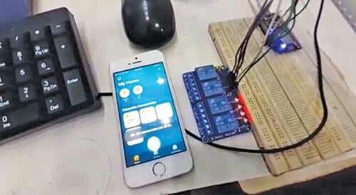
Below you can see the demo video of the project…
We came across an amazing library that could make it possible, though it had an example to control only one relay. Here is the home automation project through which you can control four appliances through four relays.
Hardware Required for ESP8266 Apple Homekit:
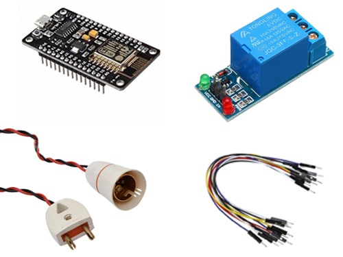
- 5V relay module
- NodeMCU board
- Jumper wires
- Bulb holder (for 230V AC)
- 60W/100W bulb
- iPhone SE or any iPhone that supports the Apple HomeKit application
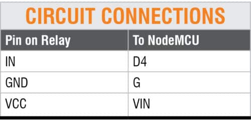
Circuit Diagram
Circuit connections are very simple. The Table shows connections between the relay module and NodeMCU.
The complete connection diagram for controlling a bulb through a relay module is shown below. You can connect the circuit in a similar way to control the remaining three electrical appliances.
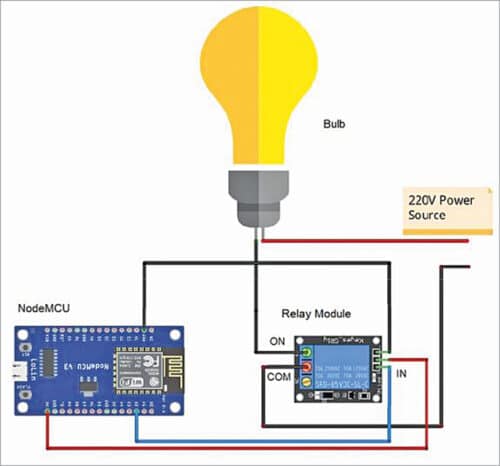
There are two wires in the bulb holder, as shown in the above image. Cut one of the wires in the middle and connect one of the cut ends to the COM pin and the other to the NO terminal of the relay module. Connect pin D2 of NodeMCU to IN pin of the relay module.
Setting up ESP8266 HomeKit
First of all Download the Arduino-HomeKit library.
After downloading, open Arduino IDE and follow the steps given below.
Step 1:
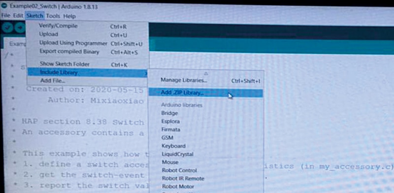
From the Arduino IDE, click on Sketch and then the Include Library option.
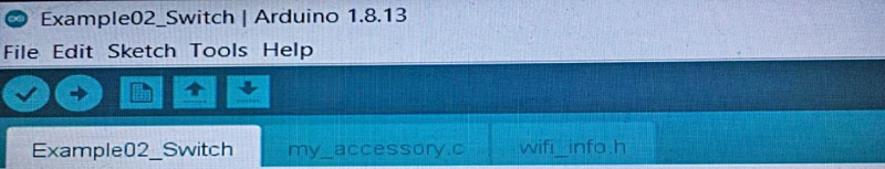
Next click on Add .Zip Library and select HomeKit-ESP8266 library. The three files Example02_Switch, my_accessory.c, and wifi_info.h will be included in the Arduino IDE.
Step 2:
Open the Example02_Switch file. The original ‘Example02_Switch.ino’ code includes only one relay module. For adding multiple (four) relays, you need to make some changes in the code, as explained in the next section.
Step 3:
In Wifi_info.h file, mention your own SSID and password.

Step 4:
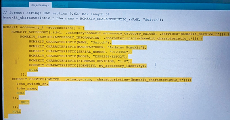
First, make some changes in the ‘my_accesory.c’ code. To add many devices, copy and paste the highlighted part as many times as the number of devices to be added to the project.
Step 5:
After adding multiple times, change the ‘id’ in the line “HOMEKIT_ACCESSORY (.id=1, .category=homekit_accessory_category_switch, .services=(homekit_service_t*[])” as shown in the below image.
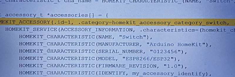
Step 6:
Change .id=1 to .id=2. If you have added the third device, change it to .id=3. So every time you copy and paste the highlighted part, increase the .id number.
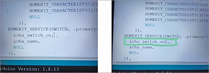
In the highlighted part you will find the “&cha_switch_on” line, as shown in the above image. This is the default code for the channel switch number. If you added a new highlighted part, change it to “&cha_switch_on2”.
You need to increase the switch number every time you add a new highlighted part.
Step 7:
Next, you will find “homekit_characteristic_t cha_switch_on= HOMEKIT_CHARACTERISTIC_(ON, false);” in the same code.
Here too, you need to add this line as many times as you have added the devices and also add the switch_on number. For example, if you added two devices, the line of code will be as follows:
homekit_characteristic_t cha_switch_on = HOMEKIT_CHARACTERISTIC_(ON, false);
homekit_characteristic_t cha_switch_on2 = HOMEKIT_CHARACTERISTIC_(ON, false);
Step 8:
Now make some changes in the Example02_Switch code. Here, you will find the line “extern “C” homekit_characteristic_t cha_switch_on;”.
You need to add this line every time you add a device and also as before you have to change switch_on to switch_on2, switch_on3, etc.
Step 9:
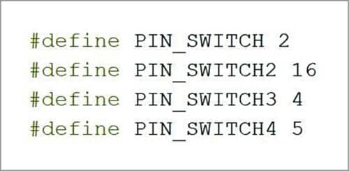
Next, you will find a “#define PIN_SWITCH 2” line of code. Copy this line and add as many times as you have added new devices and also change each pin number.
This pin actually defines the pin of the NodeMCU board where the device is connected through the relay module.
The GPIO pins defined in this project for switching the four relays are shown below.
Note that the pin 2 defined here is not the physical pin D2 of NodeMCU; it is GPIO pin 2.
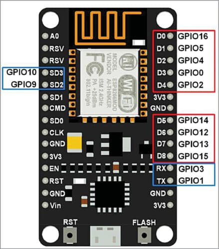
The GPIO pins are marked on the NodeMCU board.
To control four appliances, we used GPIO2, GPIO16, GPIO4, and GPIO5 pins of NodeMCU. Each GPIO pin should be connected to the corresponding relay module, as shown in the connection diagram.
Step 10:
Next is “cha_switch_on.setter = cha_switch_on_setter;” line of code.
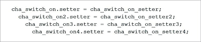
Copy this one too and add it as many times as the number of devices to be added to the project. For adding four new devices, change the switch_on and setter.
Next is the “void my_homekit_setup()” line. Inside that you will find “pinMode(PIN_SWITCH, OUTPUT); and digitalWrite(PIN_SWITCH, HIGH);”
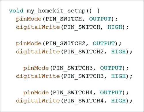
You have to add these lines as many times as you have added new devices. For four devices, you need to change the variables.
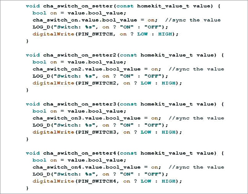
After this select the following lines:
“void cha_switch_on_setter (const homekit_value_t value) { bool on = value.bool_value;
cha_switch_on.value.bool_value = on; //sync the value LOG_D(“Switch: %s”, on ? “ON” : “OFF”);
digitalWrite(PIN_SWITCH, on ? LOW : HIGH); }”
Copy these lines and add as many times as you have added new devices. Then change the setter, PIN_SWITCH, and cha_switch_on in the code.
This is basically the .setter function to get the switch event sent from Apple’s iOS device.
Now, upload the code to the NodeMCU board.
Setting up Apple HomeKit
For apple home Automation, follow the steps given below to set up the Apple HomeKit app using Apple’s iPhone SE device.
Step 1: Download the HomeKit from App Store.
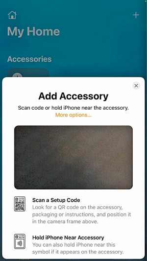
Step 2: On the top right corner, click on the plus (+) button. Select Add Accessory. You will see a pop-up window, as shown below. Select More options… to continue.
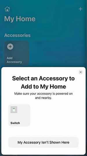
Step 3: Next, another pop-up window appears. Here you will find your “Switch” device. Click on the Switch.
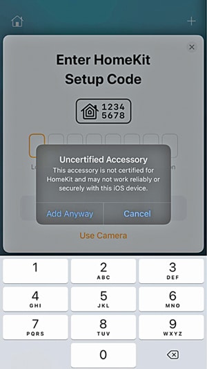
Step 4: You will see a warning message popping up. Just click on Add Anyway option.
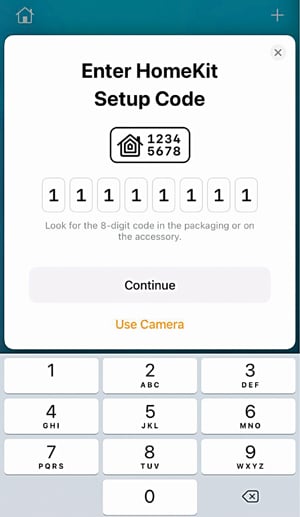
Step 5: You need to add an 8-digit setup code. Here, 11111111 is the default setup code.
Step 6: Now it will ask for a switch location. You can choose as per your setup. Here Bedroom switch is used. Click Continue to proceed with the steps.
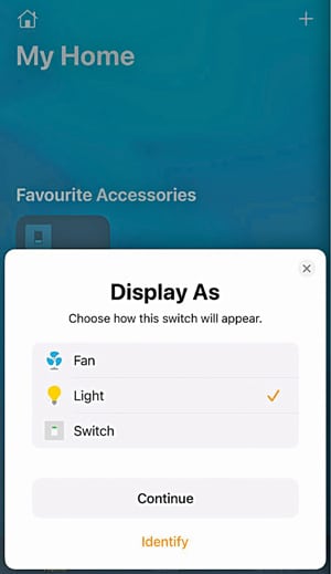
Step 7: Next, the Display AS window pops up. You can choose any of the devices listed, including the fan or light, or switch if they are connected. Then click Continue.
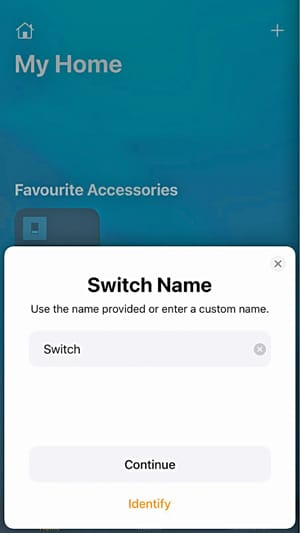
Step 8: Now it will ask for the Switch name. This feature gives you the ability to set any custom name for your switch. Then click Continue.
Step 9: Lastly, a window pops up showing that a switch has been added to your home. Click Done.
Now you can manually control all four appliances from your iPhone device by pressing the respective buttons or through voice commands. The Hey Siri feature lets you control the appliances using your own voice commands.
For example, to turn on the bedroom light, just say “Hey Siri, turn on the bedroom light.” Immediately, the app will respond with the voice “Ok, the switch is on” along with the text displayed on the app, as shown below. At the same time, the bedroom light will turn on.
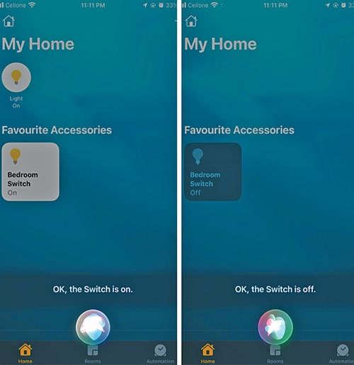
Similarly, to turn it off, say “Hey Siri, turn off the bedroom light.” The app will give an “Ok, the switch is off” voice response along with the text on the app. At the same time, the bedroom light will be turned off.
Similarly, you can control other appliances that are already connected to NodeMCU and programmed in the app.
Note: After uploading the code to NodeMCU, in case you want to make some changes in the code, first, make sure to erase the flash memory of your NodeMCU. Then only you can upload the modified code into the NodeMCU. Otherwise, the app may give a “Not available” error message.
If you face any issues or have any doubts, please feel free to ask in the comments below.
Bonus Tip: We have more such interesting Home Automation projects, you can check them too.
Rohan Barnwal is an electronics hobbyist and Youtuber. Rahul Barnwal, a B.Tech from the Indian Institute of Information Technology, Kottayam is a physics and electronics enthusiast

Hi!
It’s very interesting and useful description of “How does it work?”!
Could you explain me how to add physical-button with a callback to HomeKit?
Many thanks in advance!
Interesting project. Thank you.
You are most welcome