
IoT devices are widely used to monitor and control physical systems such as lights, fans, motors, and industrial equipment. This system extends that capability by monitoring the health and operational status of the IoT device itself using the ESP32-C3 Super Mini. The ESP32-C3 continuously monitors key parameters, including CPU usage, RAM utilisation, Wi-Fi signal strength (RSSI), chip temperature, flash memory usage, reset reason, device uptime, and Wi-Fi channel. These telemetry values are periodically published to a public MQTT broker for real-time visualisation on a smartphone dashboard. Bidirectional MQTT communication also enables remote control of the onboard LED and software resets. The system provides a practical, low-cost solution for remote diagnostics, preventive maintenance, and performance monitoring of embedded IoT devices.
POC Video Tutorial
As IoT deployments continue to grow, remote health monitoring has become increasingly important. Continuous telemetry helps identify issues such as memory leaks, poor network connectivity, overheating, and unexpected resets before they result in device failure. This improves system reliability while reducing maintenance effort.
With built-in Wi-Fi, low power consumption, and adequate processing capability, the ESP32-C3 Super Mini is well-suited for a compact health monitoring node. Combined with the lightweight MQTT protocol, it provides an efficient and scalable solution for real-time IoT device monitoring and remote management. Fig. 1 shows the ESP32-C3 IoT device health monitoring system, while the components required to build the system are listed in Table 1.
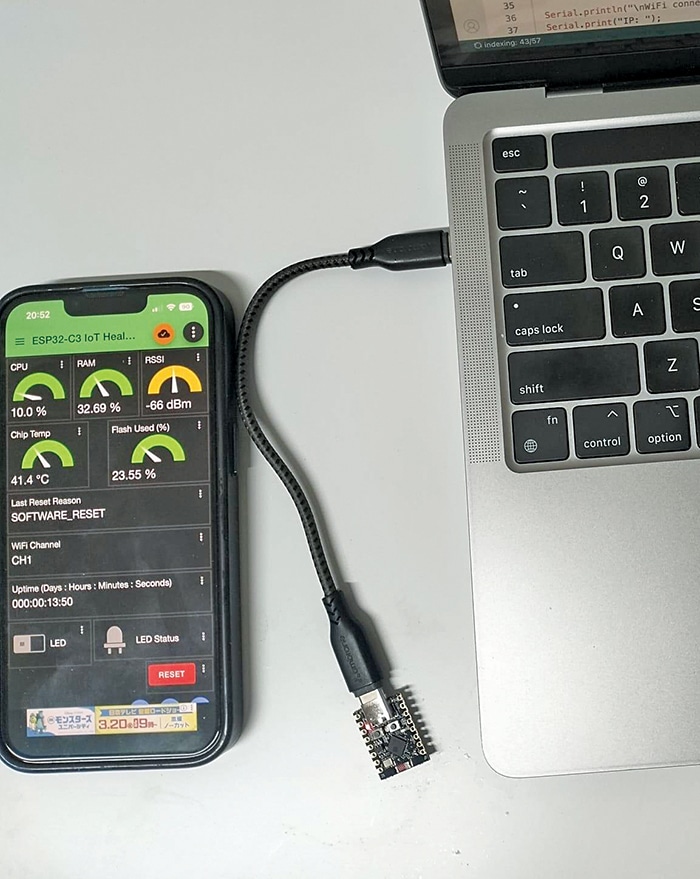
| Table 1: Bill of Materials | |
| Component | Quantity |
| ESP32-C3 super mini | 1 |
| USB Type-C cable | 1 |
| Breadboard (optional) | 1 |
| Jumper wires | As required |
| LED (onboard LED may be used) | 1 |
| Wi-Fi-enabled smartphone | 1 |
| Laptop/PC for programming | 1 |
MQTT broker configuration
This system uses the Switchsys public MQTT broker, a free MQTT broker suitable for learning, testing, and IoT prototyping. It supports standard MQTT clients over TCP on port 1883 and does not require user authentication.
Switchsys MQTT broker details:
Port: 1883 (TCP, non-TLS)
Table 2 shows the MQTT topic structure used in this system for communication between the ESP32-C3 Super Mini and the IoT MQTT Panel application.
| Table 2: MQTT topic structure | |||
| Message Description | MQTT Topic | Published By | Subscribed By |
| Telemetry | esp32c3/telemetry | ESP32-C3 super mini | IoT MQTT panel app |
| LED control | Esp32c3/led/control | IoT MQTT panel app | ESP32-C3 super mini |
| LED status | Esp32c3/led/status | ESP32-C3 super mini | IoT MQTT panel app |
| Remote reset | Esp32c3/reset | IoT MQTT panel app | ESP32-C3 super mini |
| Formatted uptime | Esp32c3/uptime | ESP32-C3 super mini | IoT MQTT panel app |
Example of a telemetry payload.
{

“cpu_usage”: 21.4,

“ram_usage”: 34.7,

“rssi”: -56,

“chip_temperature”: 45.8,

“last_reset_reason”: “POWER_ON”,

“wifi_channel”: 1,

“flash_usage”: 23.56

}
Working with the Switchsys MQTT broker
The ESP32-C3 Super Mini connects to the local Wi-Fi network and establishes an MQTT session with the Switchsys public MQTT broker. Once connected, the device periodically publishes health and system telemetry while subscribing to MQTT topics for remote control commands.
Telemetry published by the ESP32-C3 super mini
- CPU usage (%)
- RAM usage (%)
- Wi-Fi signal strength (RSSI in dBm)
- Chip temperature (°C)
- Flash memory usage (%)
- Reset reason
- Wi-Fi channel (CHx)
- Device uptime (Days:Hours:Minutes:Seconds)
- Remote LED status
Control commands subscribed by the ESP32-C3 super mini
- Remote LED control (on/off)
- Remote ESP32 reset
Software configuration
Before uploading the program to the ESP32-C3 Super Mini, update the following parameters in the source code:
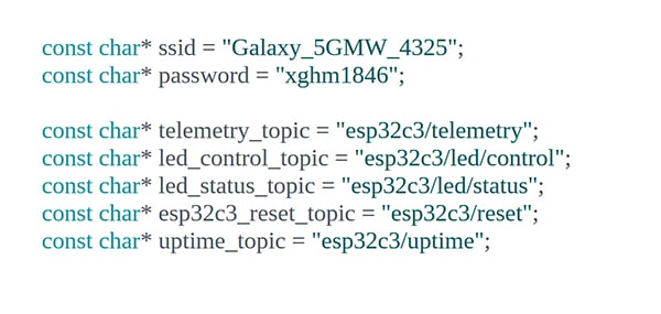
- Wi-Fi SSID and password. Replace these with the credentials of the local Wi-Fi network.
- MQTT topic names (optional). Modify the topic names if required. When using a public MQTT broker, unique topic names are recommended to prevent conflicts with topics used by other users. Appending initials, a system identifier, or another unique suffix to each topic helps avoid naming collisions.
In this system, the code is configured to publish telemetry data, LED status, and uptime information to the MQTT broker while subscribing to topics for remote LED control and device reset commands. Fig. 2 shows the Wi-Fi credentials and MQTT topic configuration defined in the ESP32-C3 source code.
CPU usage (%)
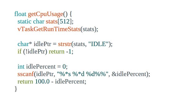
CPU usage indicates the percentage of the ESP32-C3 Super Mini’s processing capacity currently being used by running tasks. The ESP32 operates on the FreeRTOS real-time operating system (RTOS), which manages multiple tasks simultaneously.
CPU utilisation is determined by measuring the processor’s idle time. Whenever no application tasks are running, the FreeRTOS idle task executes. By monitoring the runtime of the idle task, the system estimates the percentage of time the processor is idle. The getCpuUsage() function retrieves the FreeRTOS runtime statistics, identifies the idle task, determines its idle percentage, and calculates CPU usage using the following equation:
CPU usage (%)=100−Idle Time (%)Fig. 3 shows the getCpuUsage() function used to calculate ESP32-C3 CPU usage from the FreeRTOS idle task runtime statistics.
RAM usage (%)