


 Precise measurement of line signal frequency is very important in many applications, especially in the management of power grid systems. Tasks like calibration of governors of engines that run generators in power plants need a resolution up to 0.01Hz.
Frequency is also an important parameter in load sharing among several power plants in the grid. Presented here is a line frequency meter, that does it for you.
Line Frequency Meter Concept
When the required resolution of the displayed frequency is 1Hz, the instrument becomes simple. Direct frequency counting is one of the many possible methods as shown in Fig. 1.


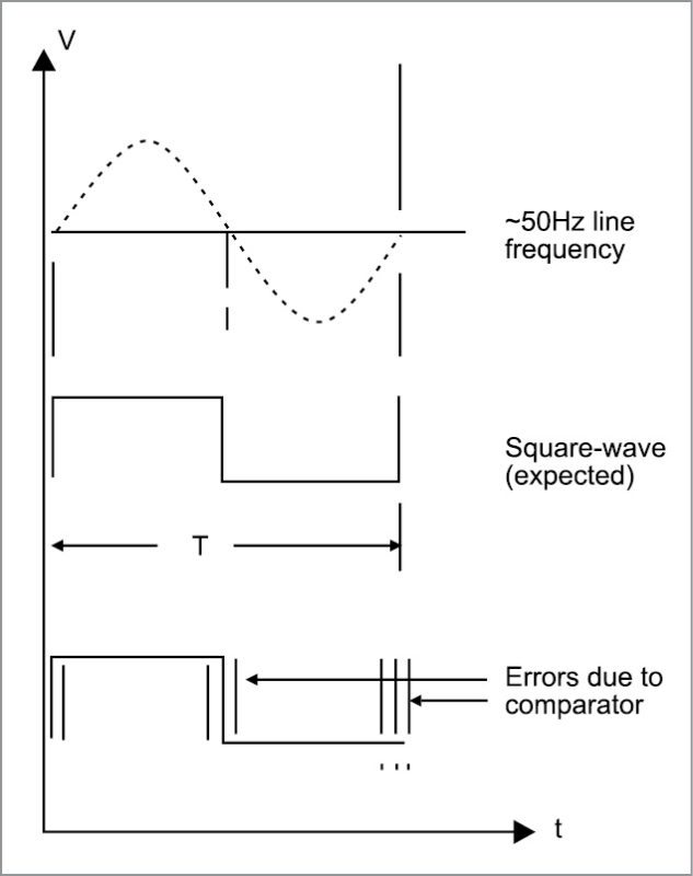
However, when the resolution required is other than 1Hz, like, say, 0.1Hz or 0.01Hz, value of frequency is obtained from its period. Period is measured in microseconds and frequency is calculated from it. But this method suffers from errors caused by zero-crossing detectors.
In Fig. 2, input conditioning is mainly a zero-crossing detector that produces a pulse for each zero crossing of the sine wave. But here, errors can be caused by comparators whose threshold value may change due to temperature.


Also, hysteresis present in the comparator can cause detection errors. Fig. 3 shows the cause of error in the measurement of the period of a signal.
Reciprocal counter is a class of counter that makes a period measurement on input signal. But it does not use a single- or multi-period counter. Instead, it uses two counters called event and time. Value of frequency can be displayed directly by taking the reciprocal of the period measured as shown in Fig. 4.

Superiority of the reciprocal counting method over other two methods is given below:
1. Integral cycle of input signal cycles is used so that ±1 quantisation error is eliminated. This prevents comparator errors from affecting accuracy.
2. Higher resolution is obtained without a long measuring time.
Principle of Operation
A generalised frequency meter with reciprocal counting is shown in Fig. 5.

An exact number of input cycles are counted in event counter and, simultaneously, the reference clock is counted in time counter for the same duration.
An equation can be written as:
Ns x Ts=Nr x Tr
where Ns is the number of cycles of the input frequency (50 counts in this case) and Ts is the period of the input signal. Nr is the number of cycles of the reference frequency counted within this time and Tr is the period of the reference clock (0.2 milliseconds or 0.2ms in this case).
Frequency of signal is given by:
Fs=1/Ts=Ns/(Nr x Tr)
=50/(Nr x 0.2ms)=250000/Nr
If line frequency is exactly 50Hz, this equation will give:
Fs = (250000/5000) = 50
That is, to obtain a resolution of 0.01Hz, value in the display will be 50.00.
Arduino Uno is an excellent platform for the measurement of line frequency using the reciprocal counting method. A simplified block diagram of the line-frequency meter is shown in Fig. 6.

In this figure, line-voltage sine-wave is converted into a square wave of TTL levels using only a transistor. This is sufficient because the event counter counts only integral cycles and that eliminates zero-crossing errors. This square wave is applied to port pin 6 of Arduino Uno.
Square-wave cycles are counted by the software and the event counter. Clock frequency for the time counter is obtained from Arduino itself by the use of Tone() function in the Arduino code as explained in software section. This signal is applied to counter T1.
1. Event counter software counts exactly 50 cycles of the input signal.
2. Time counter simultaneously counts the number of reference pulses.
3. A simple reciprocal calculation then finds the frequency.
A counter similar to the circuits based on ICL7217 or NS74C926 can be used as a four-digit display for Arduino Uno (Fig. 7). For example, if 1234 has to be displayed, all that is needed is to send 1234 clock pulses. But these counters (7217 and the like) require three signals: reset, latch and clock. That will take three pins of Arduino.
Note
A special counter named ICOUNT is available from a manufacturer in Madurai, Tamil Nadu. This counter requires only one port pin from Arduino. Reset and latch signals are automatically generated by ICOUNT. The number to be displayed is transferred from any available output port of Arduino as a train of pulses. When pulses stop to arrive, the display is updated.
Circuit and Working
Circuit diagram of the line-frequency meter with reciprocal counting is shown in Fig. 7. A 230V primary to 12V-0-12V, 300mA secondary step-down transformer (X1) is used for the power supply input and to get a signal to drive transistor BC547 (T1) that provides a square-wave output corresponding to line-frequency input.

Diode D3 applies only positive half cycles of the sine wave to base resistors (R1 and R2) of the transistor. A low-pass filter is applied to this wave so that spikes present in the line are suppressed. The transistor saturates for the value of base and collector resistors shown. This square wave is applied to input pin 6 of Arduino Uno (Board1).
Software
The code (LFM.ino) is written in Arduino programming language. Tone() function produces a 5kHz clock pulse at pin 8 of Board1, and this is connected to Timer1 input at pin 5. Clock pulse train from pin 12 of Board1 is given to the four-digit counter display module.
The +5V supply to the display module is taken from Arduino (Board1) itself as the current needed is very small. The author’s prototype with 50.08Hz line frequency having a precision of 0.01Hz is shown in Fig. 8.

ATmega328 is programmed using Arduino IDE software. Select the correct board from Tools→Board menu in Arduino IDE, and burn the program (sketch) through the standard USB port in your computer.
Download source folder: click here
P. Priyadharshini and R. Preethi are electronics hobbyists


What is the Arduino programming code for this?
the program code not working
what is the exact display module you have used?
Is the program run with tm1637 display counter?
Otherwise please write the names of the display counter.
The schematic shows that Arduino gnd is floating. Please correct.