 Some of the mosquito repellent available in the market use a toxic liquid to generate poisonous vapours in order to repel mosquitoes out of the room. Due to the continuous release of poisonous vapours into the room, after midnight the natural balance of the air composition for good health reaches or exceeds the critical level. Mostly, these vapours attack the brain through lungs and exert an anesthetic effect on mosquitoes as well as other living beings by small or greater percentage. Long exposure to these toxic vapours may cause neurological or related problems.
Here is a circuit that automatically switches on and off the mosquito repellent after preset time interval. This allows a control over the release of toxic vapours in the room.
Mosquito Repellent Circuit

The circuit turns the mosquito repellent periodically ‘on’ and ‘off’ for approximately 20 minutes each. So if you leave the mosquito repellent switched on from 10 pm to 6 am (eight hours), it will be ‘on’ for four hours and ‘off’ for four hours of the total duration. During ‘off’ time, the room air tries to balance its natural composition. Another important feature is that the circuit switches to ‘on’/‘off’ operation without producing any noise or a sound click as in a relay and hence doesn’t disturb your sleep.
Circuit operation
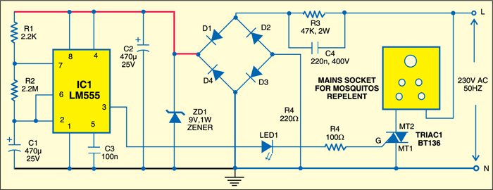
The circuit consists of a timer section built around IC 555 (IC1) and an automatic switching section using triac BT136 (TRIAC1). Power supply to the circuit is derived from the AC mains by stepping it down and rectification. The elimination of the transformer saves on space as well as money. Zener diode ZD1 and capacitor C2 provide regulated 9V DC power supply to timer IC1.
The timer section comprises resistors R1 and R2 and capacitor C1. The output of timer IC 555 is fed to the gate terminal of BT136 through series LED1 and resistor R4. When the timer output goes high, it triggers the gate of TRIAC1 and LED1 shows the ‘on’ period. During ‘off’ time, the output of IC1 goes low and hence TRIAC1 is not fired and LED1 doesn’t glow.
Construction & testing
The circuit is very compact and can be assembled on a general purpose PCB. Use an 8-pin IC base for timer IC LM555. After assembly, fit the unit inside the housing electric board where you plug in the mosquito repellent.


Please display
the Components list