


 Industrial timers are widely used in the industry for automatic controlling of electrical devices. Most timers available in the market are either complicated or poor in quality with unsatisfactory cost-to-performance ratio. This DIY industrial timer is panel-mountable and offers excellent time precision for industrial use. The 7-segment display to show counting is directly driven by the microcontroller (MCU) without driver ICs.
Circuit and working
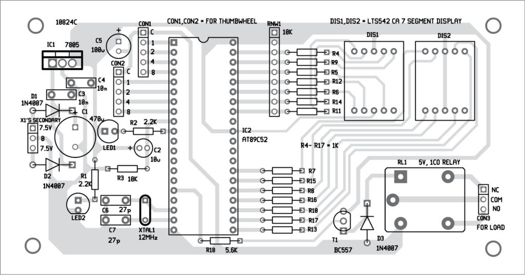
The circuit diagram of the industrial timer is shown in Fig. 1. It is built around 5V voltage regulator 7805 (IC1), AT89C52 MCU (IC2), 5V relay (RL1), two thumbwheel switches (TWS1 and TWS2) and a few discrete components.
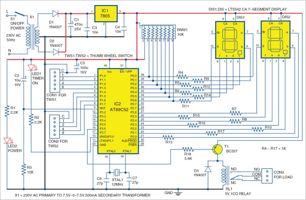
The circuit is powered by 230V AC mains. Transformer (X1) reduces 230V to 7.5V-0-7.5V. Diodes D1 and D2 are rectifier diodes, and capacitor C1 is connected as a filter. Filtered and regulated DC voltages are then fed to the circuit. AT89C52 MCU runs with 12MHz clock frequency, interfaced with two thumbwheel switches, two common-anode 7-segment displays (DIS1 and DIS2) and one 5V relay.

Transistor T1 works as a relay driver for RL1. Port pins P0 and P2 of IC2 are connected to 7-segment displays (P0 is MSB and P2 is LSB). LED2 is connected as a power-on indicator, and LED1 is connected on P3.0 pin as a timer-on indicator.
Switch S1 is used to turn on and off the power to the circuit. C4 and C5 are used for suppressing high-frequency signals generated by IC1. C6 and C7 are decoupling capacitors for the crystal. C2 and resistor R3 are power-on reset circuits for MCU IC2.
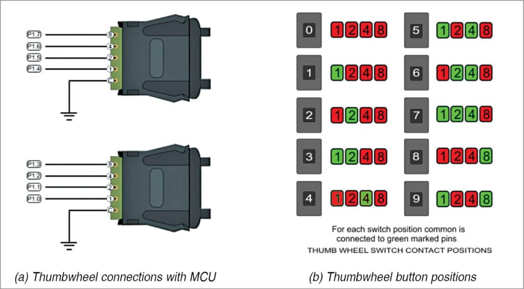
DIS1 and DIS2 are used to display time settings using TWS1 and TWS2. Details of TWS1 and TWS2 are shown in Fig. 2.
When S1 is closed, display indicates 00. After the timer starts counting up to set time, it automatically stops and the relay energises to cut off load. The display indicates the last count value till the timer restarts again.
Maximum count shown by DIS1 and DIS2 is 99 seconds. For example, to set the time as 13 seconds, first set 3 using TWS1 and then 1 using TWS2. Then, when you close S1, counter starts counting 01, 02, 03… till it reaches 13 and LED1 starts blinking. After displaying 13, the counting automatically stops, LED1 stops blinking and RL1 energises.
Software
The program code is written in C language and compiled with Kiel µvision 4 software. The main part of the program scans the settings of the thumbwheel switches and saves the data. The program starts incrementing count value from 0 to set value with a delay of one second and displays current values on the 7-segment display. RL1 gets activated on completion of the count and stays in that condition indefinitely as long as power is available.
The hex code generated using Keil software is burnt into the MCU using any suitable AT89C52 programmer.
Download Source Code
Construction and testing
An actual-size PCB layout for the industrial timer is shown in Fig. 3 and its components layout in Fig. 4.
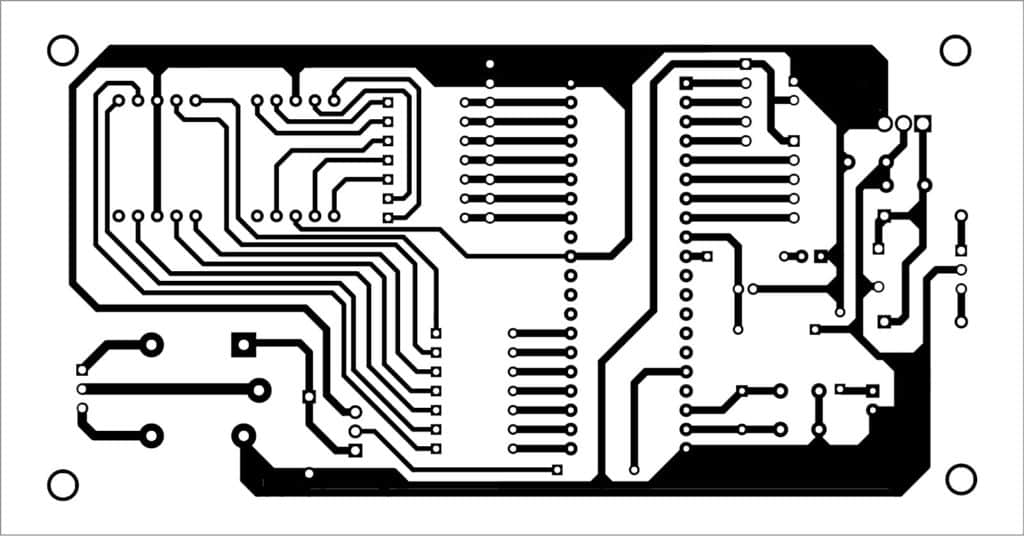
Download PCB and Component Layout PDFs: click here
Place the components on the PCB and solder these carefully. Load the hex file into the MCU and place it on the 40-pin IC base of the PCB. Connect the thumbwheel switches to the MCU as per circuit diagram.
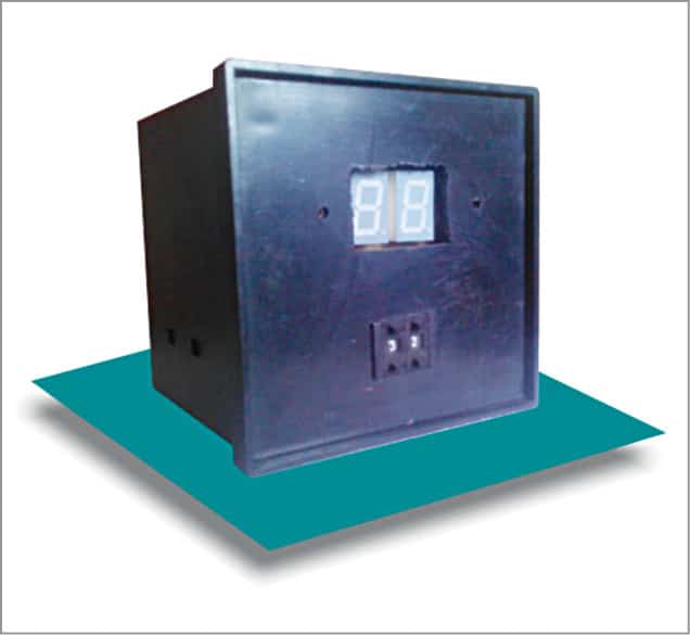
After assembling the circuit, enclose it in a suitable box. Fix LED1, LED2, TWS1, TWS2, DIS1 and DIS2 on the front side of the cabinet. Set TWS1 and TWS2 to any desired number. The author’s prototype of the industrial timer is shown in Fig. 5.
For testing, connect 230V AC to L (line) and N (neutral) and two 60W bulbs for Lamp1 and Lamp2, as shown in Fig. 6. When power is switched on by closing S1, Lamp1 glows and Lamp2 goes in off condition.
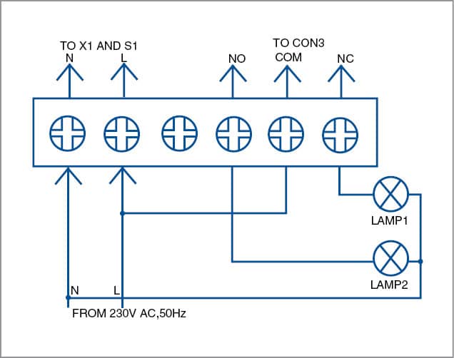
The timer starts counting from 00 in the displays, and at the same time LED1 starts blinking. When counting reaches the set value, the timer stops. Then, Lamp1 and Lamp2 conditions get toggled.
After successful testing with lamps, disconnect the lamps. Now you can connect any electrical appliance to CON3 to operate it at a particular set time.
A. Asokan Ambali is working as senior instrument mechanic at Naval Aircraft Yard, Kochi
Please i need to design and construct an energy prepaid meter that read dual power source, how can you be a help to me sir.
Plz clarify your requirements. ie. Maximum Voltage, power. Type of supply: two external supply or inverter/EB. Single or three phase. A normal energy meter can convert easily to prepaid mode.
Sir I need timer circuit with time 999 seconds and 9999 and 99999 seconds with thumbwheel switch. Please provide
Plz refer to one of my article published in EFY “precision stop watch”. A small modification in the code can change the device to a 4 digit timer. For 5 digit timer You have to assemble a 5 digit multiplexed 7seg. Display. Any counting one second step is very easy.