


Repeated or prolonged pressing of a doorbell can be disruptive, particularly in homes or offices. Visitors often press the bell multiple times in quick succession or hold it down too long, creating unnecessary disturbance.
To counter this, a timer-controlled doorbell device has been developed using two 555 timer ICs in monostable mode, combined with a relay driver and a control circuit to block repeated activations within a short interval.
POC Video Tutorial
This compact and effective system introduces a lockout period via IC2, ensuring the bell sounds only once per trigger cycle, regardless of how often the button is pressed. The timing intervals for IC1 and IC2 can be adjusted using appropriate resistor and capacitor values.

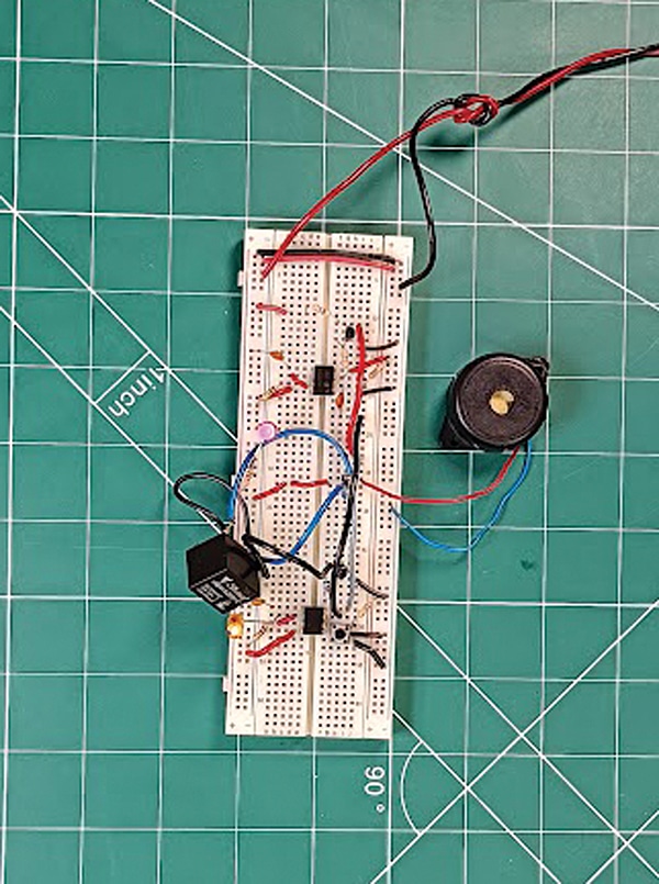
Designed with standard, low-cost components, this dual 555 timer-based device offers a simple yet intelligent solution to prevent repeated bell ringing. It adds smart control to a basic doorbell system, improving both convenience and user experience. Fig. 1 shows the prototype on a breadboard.
Circuit and Working
Fig. 2 shows the circuit diagram of the timer-controlled doorbell. The device is built using two 555 timer ICs (IC1 and IC2), both configured in monostable mode. A relay (RL1) is used to activate the doorbell, along with a pair of transistors—BC547 (T1) and 2N3904 (T2).
These transistors drive the relay and control the reset functionality of the first timer, respectively. The circuit handles multiple presses of the doorbell button, ensuring that the bell rings only once within a preset interval, regardless of how many times the button is pressed during that period.
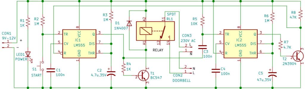
The first monostable circuit, based on IC1, is responsible for triggering the actual ringing of the doorbell. When push-button switch S1 is pressed momentarily, it triggers IC1, which outputs a high pulse for a duration determined by resistor R3 and capacitor C2. This output is fed to the base of a BC547 transistor, which functions as a relay driver. When activated, the transistor energises the relay coil, closing its contacts and powering the doorbell connected to the relay. The doorbell sounds for around 5 seconds.
This arrangement ensures that the bell rings for a fixed, short duration—even if the button is held down for an extended period. Once IC1 completes its pulse, the output goes low, turning off the relay and stopping the bell.
To prevent the doorbell from being triggered again within a short time (due to repeated pressing), a second monostable circuit built around IC2 is used. It is also configured in monostable mode and is triggered through capacitor C3 when the output of IC1 goes low after the bell has rung. IC2 then outputs a high pulse for a duration determined by resistor R6 and capacitor C5 (here it is around 50 seconds). The output of IC2 remains high for a longer duration than IC1.
This output is connected to the base of a 2N3904 transistor, which pulls the reset pin (pin 4) of IC1 low during its high state. As a result, IC1 remains disabled throughout IC2’s output pulse. Even if the push-button is pressed multiple times during this period, IC1 will not retrigger, effectively preventing the bell from sounding again.
| Part List |
| Semiconductors: IC1, IC2 – LM555 timer T1 – BC548 NPN transistor T2 – 2N3904 NPN transistor LED1 – 5mm LED D1 – 1N4007 rectifier diode Resistors (all 1/4-watt, ±5% carbon): R1, R4 – 1kΩ R2, R3, R6 – 1MΩ R5 – 10kΩ R7 – 4.7kΩ R8 – 47kΩ Capacitors: C1, C3, C4 – 100nF ceramic disc C2 – 4.7µF, 25V electrolytic C5 – 47µF, 25V electrolytic Miscellaneous: CON1 – 2-pin connector Battery – 9V-12V battery/adaptor S1 – Push-to-make switch RL1 – 9V/12V SPDT relay |
Construction and Testing
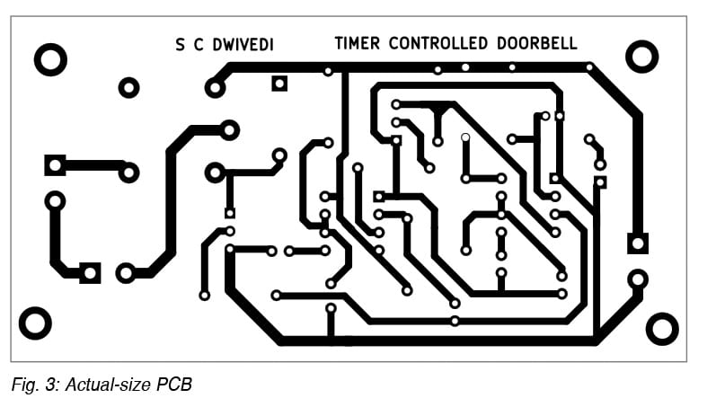
An actual-size, single-sided PCB (printed circuit board) layout for the timer-controlled doorbell is shown in Fig. 3, with the component layout in Fig. 4. After assembling the components on the PCB, place the device in a suitable cabinet, ensuring that appropriate openings are provided at the rear for mounting and ventilation. This secures the unit and helps maintain operational safety.

Alternatively, if a custom PCB is not available, the circuit can be assembled on a general-purpose PCB. Once completed, the device may be housed in a durable plastic enclosure. Ensure that the box accommodates the bell and all associated components securely, with adequate space for wiring and ventilation. A proper enclosure keeps the device safe from dust, moisture, and accidental damage, while ensuring reliable operation. All connections should be double-checked before powering the system.
How to Install?
Installing this timer-controlled doorbell device is straightforward, but a careful and deliberate approach is necessary, particularly when installing it in a common area. Begin by taking the assembled PCB and connecting a pair of twin wires from the PCB to switch S1. Mount the switch near the main entrance gate. Connect the doorbell and a 230V AC power supply to the respective two-pin connectors, CON2 and CON3.
Position the assembled device in a suitable location inside the home, ensuring that the doorbell’s sound is audible throughout the premises when someone presses switch S1. Use insulated wires to route the power connection safely along the mains terminals, avoiding exposed wiring. Confirm all connections are secure and test the system thoroughly before finalising the installation. This setup enhances home security and convenience with minimal complexity.
Bonus: You can watch a step-by-step video tutorial.
S.C. Dwivedi is an electronics enthusiast and circuit designer at EFY
