


 The main objective is to design a MODEL ATM machine using RFID and GSM technologies. Here we design a model of how really ATM machine works, with some limited features. Also in this model we use wireless smart card (RFID).
This project uses a microcontroller from 8051 family. The primary objective of this project is to detect SMART CARD and we can withdraw amount from it. To demonstrate this project, we assign a default amount (10,000) to a specific smart card, when we check that card with RFID READER we can withdraw and check available balance in the card.
The program thereafter takes over to send an SMS through GSM modem interfaced through TX, RX pin to the microcontroller. An LCD is also interfaced with the MC to display required information. Thus, the proposed model is designed to demonstrate a working model of bank ATM machine. In future we can interface with cash machine to withdraw specific amount.

Circuit and working:
Components used:
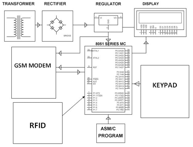
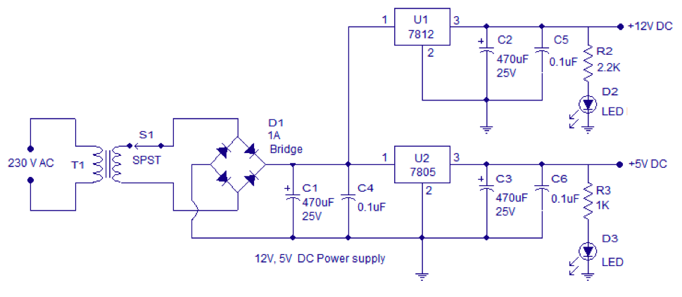
1. Power supply ( 12v step down transformer, rectifier, 7805 voltage regulator, capacitor, resistor, LED)
2. 89s52 microcontroller
3. 16×2 lcd
4. SIM900 GSM module
5. RFID READER (EM 18) & TAG
6. 4×3 matrix keypad
7. Switches and Buzzer

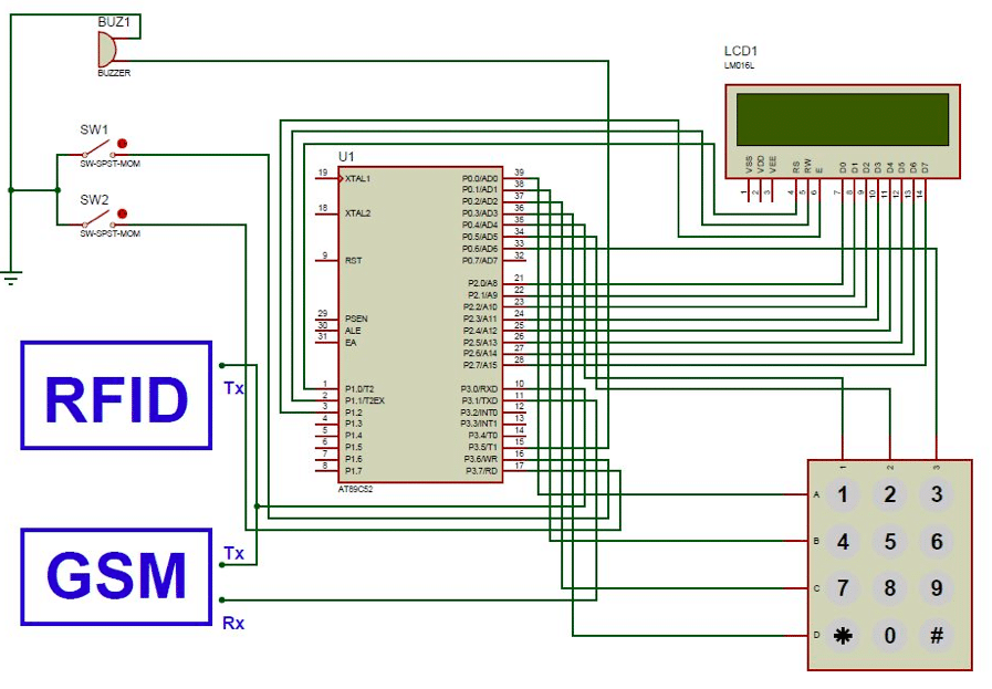
Circuit Diagram:
Circuit Working:
AT89S52 is an 8-bit MCU with 8k flash, 256 bytes of RAM, 40 pins with 32 I/O pins. It controls all the interfaced components according to the program written. Its receives the ATM card data from reader, check with its memory, display with LCD, and send SMS through GSM module. We can also check balance as well as withdraw amount using 2 switches interfaced with microcontroller. If unauthorized card shown, then buzzer will be activated.
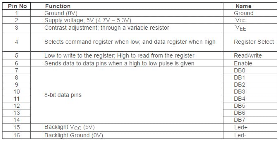
16×2 LCD (Liquid Crystal Display) screen is an electronic display module and finds a wide range of applications. These modules are preferred over seven segments and other multi segment LEDs. The reasons being;
LCDs are economical; easily programmable; have no limitation of displaying special & even custom characters (unlike in seven segments), animations and so on. A 16×2 LCD means it can display 16 characters per line and there are 2 such lines. In this LCD each character is displayed in 5×7 pixel matrix. This LCD has two registers, namely, Command and Data. It was used to display card authentication, Balance Check and Withdraw Option.
4×3 Matrix Keypad:
Keypads are a part of HMI or Human Machine Interface and play really important role in a small embedded system where human interaction or human input is needed. We make the coloums as i/p and we drive the rows making them o/p, this whole procedure of reading the keyboard is called scanning.
To detect which key is pressed from the matrix, we make row lines low one by one and read the columns. Let’s say we first make Row1 low, then read the columns. If any of the key in row1 is pressed will make the corresponding column as low i.e. if second key is pressed in Row1, then column2 will give low. So, we come to know that key 2 of Row1 is pressed. This is how scanning is done.
Keypad was used to Enter amount to be Withdrawn. We are programmed it like this to entered amount must be in 4 digits. If you want to withdraw 400 you have to enter 0400. ‘#’ key used for Enter option.
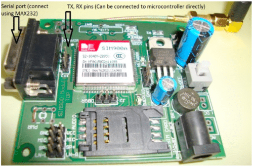
SIM900 GSM Module: GSM module is used in many communication devices which are based on GSM (Global System for Mobile Communications) technology. GSM module only understands AT commands, and can respond accordingly. The most basic command is “AT”, if GSM respond OK then it is working well otherwise it respond with “ERROR”. There are various AT commands like ATA for answer a call, ATD to dial a call, AT+CMGR to read the message, AT+CMGS to send the sms etc. AT commands should be followed by Carriage return i.e. \r (0D in hex), like “AT+CMGS\r”. We can use GSM module using these commands. We use microcontroller’s serial port to communicate with GSM, means using PIN 10 (RXD) and 11 (TXD).
GSM MODULE was used to send transaction alert to the user about the amount withdrawn from its account.
RFID Reader: An RFID (Radio-frequency identification and detection) reader is a device which is used to communicate with RFID tags by receiving and transmitting signals. These signals use radio waves for wireless communication. The identification is done through a unique serial number.
EM18 RFID reader used for scanning RFID based ATM card. It detects the card and sends the card information to Microcontroller.
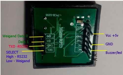 EM18 RFID READER
Power supply: All the components are DC components, so we must convert AC supply to DC with 12v stepdown transformer & a full-wave bridge rectifier. We have the requirement of 5V for LCD, Microcontroller, RFID, BUZZER & 12v for GSM MODULE. To generate different voltage, we use Voltage regulator 7805 & 7812.
Software
We are using C program to control the hardware. Keil Compiler is used for compiling the code and progisp with usb programmer is used to burn the program in the microcontroller’s ROM memory. The C program and its hex file are available for download
Functions used in program:
Delay() – This function used to generate a delay of required time.
Lcdcmd() – Used for sending command to LCD.
Lcddata() – Used for sending DATA to LCD.
Lcd_num() – Used for Display numbers on LCD.
Lcdstring() – Used for Display string on LCD.
Lcd_init() – Initialize the LCD for displaying content.
Uart_init() – Initialize serial communication with peripheral devices.
Rxdata() – Receives data from RFID reader and stores in a variable.
Keypad() – Reads the data entered from Keypad.
Accept() – If correct PIN entered it shows authentication.
Wrong() – It displays if wrong PIN entered.
My_atoi() – ASCII to integer function used for convert string to integer.
Main() – It contents the whole program.
Construction and testing
By following the circuit diagram shown above we can design PCB using Proteus software else we can design the circuit using dotted board also. Assembling circuits on PCB minimizes the time and error.
Firstly, you must connect all the components according to circuit diagram provided.
16×2 LCD:
connect 8 data pins of LCD with P2 of 89s52 microcontroller D0 with P2.0 and so on. RS, RW & EN connect with P1^0, P1^1 & P1^2 respectively. Pin no 1& 16 of LCD connect with ground and Pin no. 2&15 connect with 5v supply. Pin 3 will be connected with a variable resistor for adjusting brightness. circuit diagram of LCD and 8051 MC connection is shown below.

4×3 matrix Keypad:
A matrix keypad has 7 pins. 4 pins for 4 rows and 3 pins for 3 columns.4 rows are connected to P0^0 to P0^3 and 3 columns are connected with P0^4 to P0^6 of MC.
SIM900 GSM Module:
GSM module have 3 pins named Tx, Rx and GND available on the module. We connect Tx pin of GSM to Rx pin(P3^0) of MC and Rx pin of GSM with Tx pin(P3^1) of MC. We also must put a SIM inside the microcontroller with balance or SMS pack. Check the network LED on module and if network available then modem is now ready.
EM18 RFID Reader & Tag:
Only Tx pin of reader will be connected to Rx pin of MC. Any RFID tag can be used but we must know its ID so that we can enter it to the program and assign a pin to it.
SW1, SW2 AND Buzzer:
SW1 used for check the available balance and SW2 used for withdraw amount from the card. SW1 & SW2 are connected to P3^6 & P3^7 respectively. Buzzer is connected to P3^5 to alert unauthorized access.


Hi can this project be done by using pic 16F877a and thanks in advance