


This circuit lets you wirelessly control an appliance from a remote place by using a wireless doorbell. The appliance is triggered by the signal from the transmitter of the wireless doorbell and turns off automatically after the preset time period.
Circuit and working
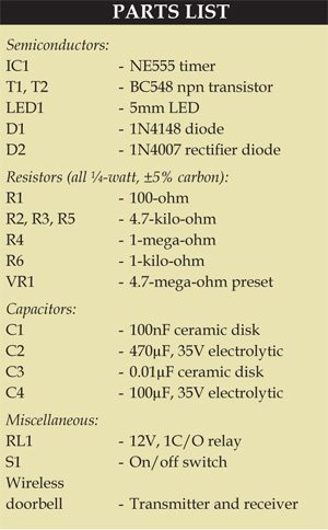
The circuit comprises a doorbell (DB1), timer NE555 (IC1) and a few discrete components. The audio output from the battery-powered doorbell receiver is connected to series resistor R1, then AC coupled to the base of npn transistor BC548 (T1) using capacitor C1 and resistor R2. Diode D1 clamps negative excursions of the signal to about 0.6V below ground to prevent damage to transistor T1, which is configured as a common-emitter amplifier with a 4.7-kilo-ohm collector load.
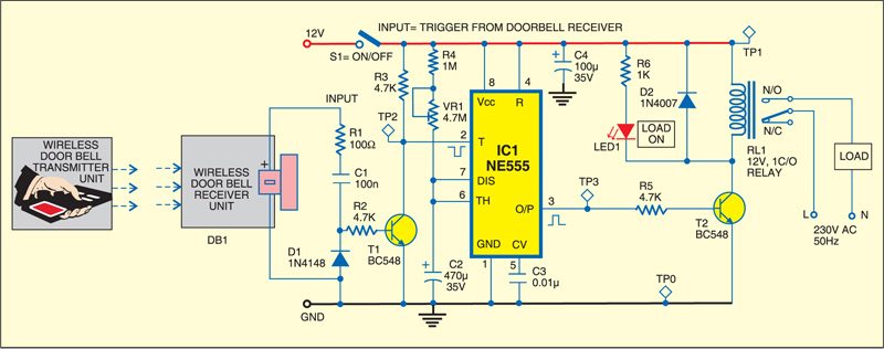
 When the doorbell rings, it produces an AC signal, which is rectified by diode D1. Transistor T2 conducts, pulling its collector low. This high-to-low transition triggers timer IC1, which is configured in monostable mode. The output of IC1 goes high for a time period that can be set between 8 and 50 minutes using trimpot VR1. This high output triggers relay RL1 to switch on the appliance.

Working of the circuit is simple. Press the wireless transmitter button to switch on the appliance for the preset time period. LED1 glows to indicate that the appliance is ‘on.’ The appliance will automatically turn off after the preset time period.
Construction and testing
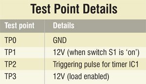
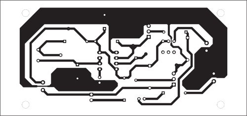
An actual-size, single-side PCB for the remote control using wireless doorbell is shown in Fig. 2 and its component layout in Fig. 3. Assemble the circuit on a PCB and connect LED1 and switch S1 at suitable place. Use a suitable 8-pin IC socket for mounting timer NE555 IC.

Download PCB and component layout PDFs: click here
Use relay RL1 with contact current rating capable of carrying the load current.
Push switch S1 to ‘on’ position and verify 12V at TP1 with respect to TP0. Press transmitter button and verify high-to-low triggering pulse at TP2 with an oscilloscope. Also verify whether TP3 is high for the preset time period.

We have also built the touchless Arduino Doorbellto protect from the corona. This doorbell only works if the visitor’s hands are sanitized.

sy prlukn litar.. komponen, snrai komponen dan papan pcb. utk projek tahun akhir
Sila huraikan pertanyaan anda
PLS, Hw can microcontroller be used in implementing a wireless doorbell