


The demand for convenient and reliable switching systems is increasing across homes, offices, and industrial environments. Conventional methods, such as wired switches and infrared (IR) remotes, have clear limitations: wired systems require complex installation and lack mobility, while IR control is effective only over short distances and requires a direct line of sight. Radio frequency (RF) technology overcomes these constraints by enabling longer-range, robust wireless communication, making it well-suited for automation.
This RF-based relay control system enables safe and efficient switching of AC loads, including lights, fans, and pumps. Typical operating range is 30-50 metres indoors and up to 100 metres in open outdoor areas, depending on antenna quality and installation conditions.
The system is highly adaptable, supporting home automation for household appliances, utility and security applications such as pumps and alarms, garage door control, and industrial tasks where equipment needs to be operated from a safe distance.

RF-based Relay Control System – Circuit and working
The system consists of two primary units: the transmitter and the receiver.
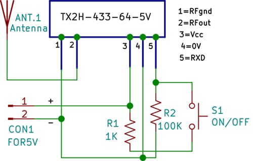
Transmitter unit
The transmitter is a compact, battery-powered circuit equipped with a push-button that sends control commands. It is built around the TX2H-433-64 RF module, operating at 433.92MHz, and powered by a regulated +5V DC supply, which can be provided by a rechargeable battery, coin-cell arrangement, or USB adaptor.
Pressing switch S1 applies a logic high signal to the RF module, causing it to transmit a modulated 433MHz carrier wave. The signal is emitted through a wire antenna, approximately 17 centimetres long, which corresponds to a quarter wavelength at this frequency. A telescopic antenna may be used if an extended range is required.
Resistors R1 (1kΩ) and R2 (100kΩ) stabilise the input signal to prevent false triggers. The transmitter assembly can be housed easily inside a compact enclosure.
Receiver unit
Fig. 2 shows the receiver unit. It uses the RX2A-433-64 RF module to detect the transmitted signal. The signal is amplified by transistor BC107 (T1) and then supplied to a CD4027 dual J-K flip-flop integrated circuit (IC1A) configured as a bistable latch. Each activation of switch S1 at the transmitter toggles the output state of the flip-flop, thereby switching the load on or off.
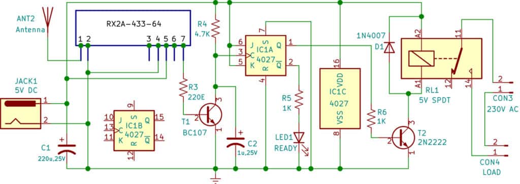
Since the flip-flop output cannot directly drive the relay, a relay driver transistor 2N2219 (T2) is used. Transistor T2 supplies sufficient current to energise the relay coil (RL1). When T2 conducts, current flows through the relay coil, activating it and switching the connected AC load. A 5V SPDT (single-pole double-throw) is used to control a 230V AC appliance such as a lamp, fan, or small motor.
The diode 1N4007(D1) is connected across the relay coil as a flyback diode to absorb the back EMF generated when the relay is de-energised, protecting the transistor from voltage spikes. LED1 serves as a status indicator that glows when the system is ready to use. When LED1 is off, it means the relay is energised and the load is on. Capacitors C1 (220µF), and C2 (1µF) filter the power supply and suppress high-frequency noise, ensuring stable receiver performance. Resistors R3, R4, R5, and R6 provide biasing for the transistors and limit the current through LEDs and IC pins, thereby enhancing the circuit’s stability.
When the transmitter sends an RF signal, the RX2A module demodulates it and passes the digital output to the CD4027 flip-flop via T1. Each valid signal toggles the flip-flop output, which drives T2 to energise or de-energise the relay. The relay contacts then switch the 230V AC load on or off.
It allows a single button to switch a device on or off alternately. The relay ensures isolation between low-voltage circuitry and the AC load for safety.
| Part List |
| Semiconductors: IC1 – 4027 dual J K flip-flop T1 – BC107 npn transistor T2 – 2N2222 npn transistor D1 – 1N4007 rectifier diode Resistors (all 1/4-watt, ±5% carbon): R1, R5, R6 – 1kΩ R2 – 100kΩ R3 – 220Ω R4 – 4.7kΩ Capacitors: C1 – 220µF, 25V electrolytic C2 – 1µF, 25V electrolytic Miscellaneous: CON1, CON2, CON3 – 2-pin connector S1 – Push-to-on switch RL1 – 5V single-pole, double- throw relay ANT1, ANT2 – 17cm long wire – TX2H-433-64-5V transmitter – RX2A-433-64 receiver – Load (60-watt bulb) |
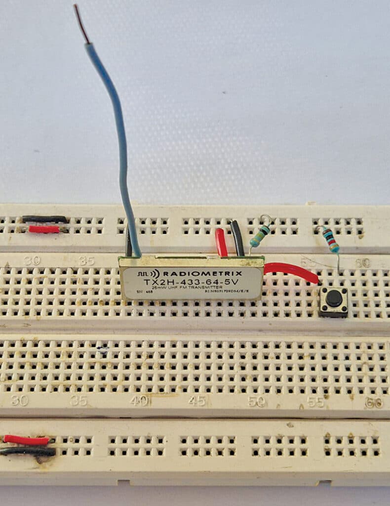
Construction and Testing
Construction begins with assembling the transmitter on a breadboard or a general-purpose PCB. Mount the TX2H-433-64 module, push-button switch S1, and the required resistors, then solder a 17-centimetre antenna wire to the RF output. Place the completed transmitter inside a compact insulated enclosure.
The receiver should be assembled on a separate breadboard or PCB. Install the RX2A-433-64 module, CD4027 IC, transistors, capacitors, resistors, relay, and flyback diode. Fit LED1 for power and status indication. Power the receiver using a regulated +5V DC adaptor. Connect the relay output to the 230V AC load through terminal blocks. Place the completed receiver unit in an insulated housing with terminals labelled appropriately.
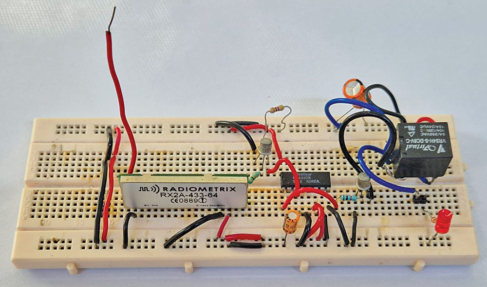
After that, assemble the RX2A-433-64 module, CD4027 flip-flop IC, and driver transistors on another breadboard. Alternatively, you can construct on a general-purpose PCB or a custom compact PCB for durability. Mount the 5V SPDT relay with a flyback diode for protection, and add the required capacitors and resistors for filtering, biasing, and noise suppression. Install LED1 to indicate system activity. Power the circuit with a regulated 5V DC adaptor, and connect the relay contacts to a 230V AC appliance (such as a lamp or fan) through terminal blocks (CON2 and CON3). Finally, house the assembly in an insulated plastic enclosure with clearly marked input and output terminals for safe use.
For testing, power the transmitter using a 5V battery and the receiver using a 5V adaptor. Connect a 60-watt lamp or similar appliance to the relay output. Press switch S1 to toggle the load on and off. Proper antenna positioning improves operational range. The system typically functions reliably up to 50 metres indoors and up to 100 metres in open areas. Suitable safety precautions must be taken when working with AC mains connections.
Bonus: You can watch the tutorial video for this DIY project below.
It would be great if you could tell us where to buy the RF modules RX2A-433-64 and
TX2H-433-64. apparently these are made by Radiometrix and not available in India.
Indicative prices would be helpful too.
You may contact APC Technology
To purchase RF modules
RX2A-433-64 and TX2H-433-64
Mobile No.: 09999025504