


Here is a simple project of FM Radio Receiver which is build around an NPN transistor Q1 BF 494 and 16-pin IC KA2247. Most FM Radio operates on 10.7 MHz IF frequency and uses 10.7MHz ceramic filter and 10.7 MHz IFT coil. As these components (10.7 MHz ceramic filter and 10.7 MHz IFT coil) used on FM radio are hard to find. So, this Simple FM Radio Receiver Using KA2247 is based on 5.5 MHz IF frequency and uses a 5.5MHz ceramic filter and 5.5 MHz IFT coil which are easily available in market and also can be taken off from old Black & white TV set, Audio/Video Transmitter e.t.c. You can also use a SW2 coil used on a SW2 radio receiver set instate a 5.5 MHz IFT coil or you can made your own.
Circuit Description
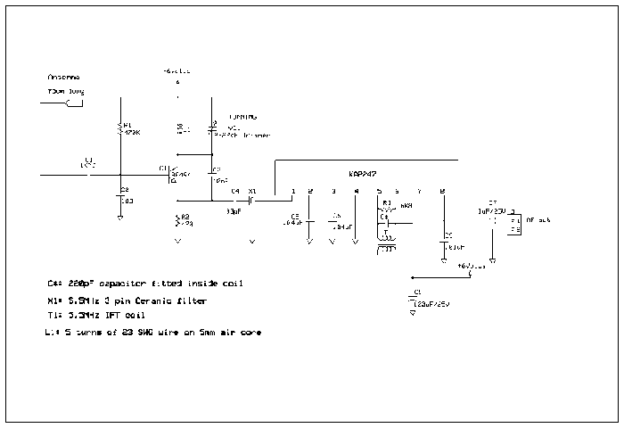
A circuit diagram given is a straight forward. First part of a circuit is build around an NPN transistor Q1 BF 494. An RF 88-108 MHz amplifier, Oscillator of frequency between 93.5 MHz-113.5MHz and Mixer stage will mixes an incoming frequency (88-108MHz) with an oscillator frequency (93.5 MHz-113.5 MHz) and gives an output IF frequency of 5.5 MHz
Resistor R1 (470K) is connected to base of Q1 and +6Volts. Resistor R2 (470) is connected to emitter and ground. Capacitor C1 (1Kpf) is connected to antenna and a base of an NPN transistor Q1 BF 494. Capacitor C2 (103) is connected between base Q1 (BF494) and ground. Capacitor C3 (10pF) is connected between an emitter and collector of Q1 BF 494.

Coil L1 (5 turns of 23 SWG wire on 5mm air core) and a trimmer capacitor VC1 (2-22pF) is connected in parallel and connected to a collector of an NPN transistor Q1 (BF 494) and +6Volts.
Capacitor C4 (33pF) is connected to an emitter of Q1 (BF 494) and to a first pin of 3-pin 5.5 MHz ceramic filter. A 2nd or middle pin of 5.5 MHz ceramic filter is grounded. A third pin is connected to pin 1 of IC1 KA2247. Pin 2 of IC1 is connected to ground with a capacitor C5 (.04uF). Pin 3 is connected to ground through a capacitor C6 (.04uF) .Pin 4 is connected to ground. Pin 5 and 6 are connected to a resistor R3 (6K8). A 5.5MHz IFT coil is also connected between pin 5 and 6. Pin 7 is not connected. Pin 8 is connected to 2-pin connected through an electrolytic capacitor C7. A capacitor C9 (.01uF) is connected to pin 8 and ground. Pin 6 is connected to +6 Volts supply and is connected to a positive terminal of electrolytic capacitor C8 100uF/25) and ground.
Construction
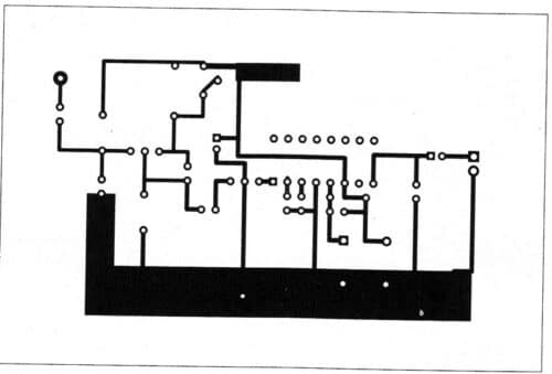
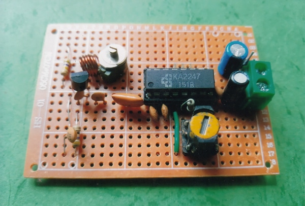
You can use a PCB board (given in an article) or you may use a 5cm* 7cm veroboard for your FM radio receiver. You may use a 75cm long wire for your antenna. Take an IC (16-pin) socket I and place it on a middle of your veroboard. Now take all other components like NPN transistor Q1 BF 494, ceramic capacitors, tunning capacitor VC1, resistors, ceramic filter (5.5MHz ceramic filter), 5.5MHz IFT coil e.t.c.
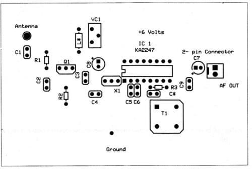
Next we will build a coil L1 and this can be made by giving 5 turns of 23 SWG wire on 5mm air core. Now also place this coil L1 on a veroboard.
Now place an IC KA 2247 on 16-pin and place it on a middle of your veroboard. Also place a 2-pin connector on a right side of a veroboard of size of 5cm*7cm.
Calibration and Adjustment
Next stage is calibration and adjustment. Now connect an output terminal of your FM radio to a working mono audio amplifier. Connect a speaker to your amplifier.
Take a 6Volts battery and connect it to your FM radio. You will hear a hissing sound from your amplifier. Now your FM radio receiver is working. Turn on a volume to middle of audio amplifier. Take a plastic screwdriver and gently tune a VC1 (2-22pF) tuning until you catch a stations. So, your FM Radio Receiver is working and ready for using.*
Parts-List
Semiconductor
Q1: NPN transistor BF 494
IC1: KA 2247
Ceramic Filter: 5.5 MHz 3-pin ceramic filter
Tuning capacitor: 2-22pF trimmer
5.5MHz IFT Coil
Resistors
R1: 470K
R2:470
R3: 6K8
Capacitors and electrolytic circuit
C1: 1KPf
C2:103
C3:10pF
C4: 33pF
C5:.04uF
C6:.04uF
C9:.01uF
C7: 1uf/25V
C8: 100uF/25V
Miscellaneous
16-pin IC socket, 5.5 MHz IFT coil, 2-pin connector, 5*7cm verobord, 75cm long wire, 6Volts etc.