


This handy remote control tester circuit for testing infrared-based remote control transmitters used for TVs and VCRs etc. The circuit is built around 7805 IC, IR sensor module and other easily available components.
Remote control tester circuit
The IR signals from a remote control transmitter are sensed by the IR sensor module in the tester and its output at pin 2 goes low. This, in turn, switches on transistor T1 and causes LED1 to blink. At the same time, the buzzer beeps at the same rate as the incoming signals from the remote control transmitter. The pressing of different buttons on the remote control will result in different pulse rates which would change the rate at which the LED blinks or the buzzer beeps.
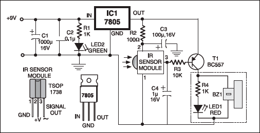
When no signal is sensed by the sensor module, output pin 2 of the sensor goes high and, as a result, transistor T1 switches off and hence LED1 and buzzer BZ1 go off. This circuit requires a 5V regulated power supply which can be obtained from 9V eliminator and connected to the circuit through a jack.

Capacitor C1 smoothes DC input while capacitor C2 suppresses any spikes appearing in the input supply.
Proper grounding of the metal case will ensure that the electromagnetic emissions which are produced by tube-lights and electronic ballasts etc (which lie within the bandwidth of receiver circuit). The proposed layout of the box containing the circuit is shown in the figure. The 9- volt DC supply from the eliminator can be fed into the jack using a banana – type plug.

The article was first published in January 2010 and has recently been updated.

PCB layout Please