


Struggling with precise cooking, safety and false touch errors, single-plate induction cooktops challenge engineers. Discover how a smart controller solves it all.
High-power single-plate induction cooktops present several challenges for design engineers. Achieving precise power control is difficult, making simmering or low-power cooking unreliable. Managing safe operation under varying line voltages and currents is critical to prevent damage to the cooktop, cookware, and electronic components. Accurate user input is hard to maintain, especially under wet conditions, as many touch systems fail or give false triggers. Engineers also face challenges in meeting efficiency targets while keeping standby power low, all within a compact, cost-effective system. Over-temperature and overcurrent conditions must be detected and mitigated to ensure safety, which often requires complex circuitry and multiple sensors.
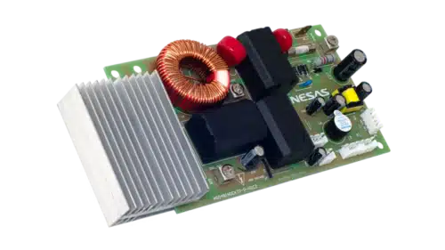
AS048-EVK, the reference design from Renesas addresses these challenges using a single-chip induction controller and IGBT driver. It allows power adjustment in ±10W steps, enabling precise simmering and controlled cooking. Over-temperature protection is integrated via three negative temperature coefficient sensors, reducing the need for external safety circuits. The human-machine interface card provides a low-pin-count interface with multiple matrix switches, LED indicators, and a 7-segment display. Capacitive touch sensing ensures robust detection even in wet conditions, preventing false inputs. The interface board communicates with the heating board to transmit mode and power settings accurately.

Power management is split across two paths after passing through the EMI filter. One path feeds the switching power circuit, while the other drives the resonance circuit, which serves as the main heating power source. The mains AC input includes a diode bridge, storage capacitors, EMI-reduction choke, and safety components such as fuses, fusible resistors, MOVs, and X-capacitors. The input surge section includes surge suppression, and fuses provide reliable overcurrent protection. The bridge rectifier converts AC to DC to power the resonance circuit efficiently.
The switching buck regulator delivers power to the controller IC and the cooling fan. Constant off-time control is used for heavy loads, and pulse frequency modulation for light loads achieves high efficiency and ultra-low standby power. The switching power circuit provides separate voltage rails for the fan, controller, buzzer, and interface board. The controller also supplies voltage to peripheral circuits, including cooktop surface and IGBT over-temperature protection circuits.
Real-time current and voltage detection circuits monitor operating conditions, providing input to adjust the IGBT in real time for precise power output. These circuits also supply reference signals for over/under-voltage and overcurrent protection, ensuring reliable and safe operation. The controller detects the presence of a pot, measures input line voltage, and switches to constant power or constant current operation accordingly. It drives the LC circuit formed by the heating element and resonant capacitor, modulating pulse timing to maintain requested output. When output power is low and zero-voltage switching is not possible, the IGBT collector voltage is monitored each cycle to prevent overheating from excessive switching losses.
Renesas has tested this reference design. It comes with a bill of materials (BOM), schematics, assembly drawing, printed circuit board (PCB) layout, and more. The company’s website has additional data about the reference design. To read more about this reference design, click here.