


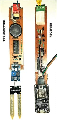
 This is an Internet of Things (IoT) based irrigation system that automatically turns on water-pump when soil moisture in the field goes below the set threshold level. It has three parts—transmitter, receiver, and the IoT system—as may be seen from its block diagram in Fig. 1.

Circuit and working
Besides the IoT, the circuit comprises transmitter and receiver whose diagrams are shown in Fig. 2 and Fig. 3, respectively.
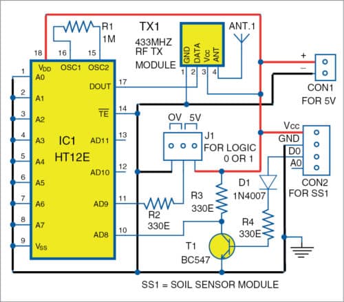
Transmitter
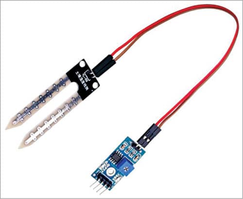
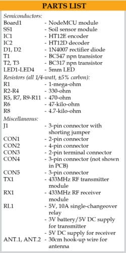
The transmitter is built around 433MHz RF transmitter module (TX1), encoder HT12E (IC1), and transistor BC547 (T1). It is installed in the field along with soil moisture sensor (SS1). The sensor’s signal is transmitted by TX1 to the receiver, which is installed nearby—within a few metres from the transmitter. The transmitter works off 5V DC supply.

Threshold level of the soil moisture can be set using the in-built pot in soil sensor module. When soil moisture in the field goes below the threshold level, the sensor produces active low (0V) signal, which goes to the base of inverting transistor T1. Encoder IC1 receives active-high signal at pin 10 (AD8) from collector of T1 and generates serial data at pin 17 (DOUT) with its address pins A0 through A7 connected to ground. The modulated ASK RF signal from DOUT is transmitted by TX1 module at 433MHz frequency. J1 is used for optional sensor input for an optional motor in the receiver circuit.
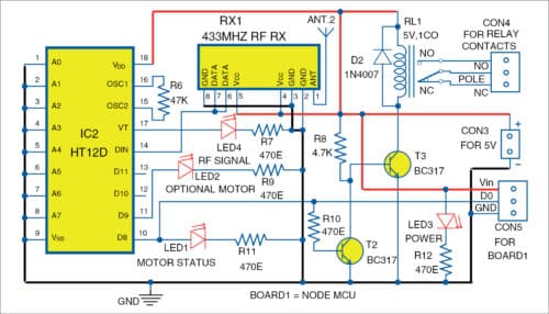
Receiver
The receiver comprises 433MHz RF receiver module (RX1), decoder HT12D (IC2), two BC317 transistors (T2 and T3), a 5V single-changeover relay (RL1), and NodeMCU (Board1). This receiver also operates off a 5V DC supply.
The signal from transmitter is received by 433MHz receiver module RX1. Decoder HT12D, with address pins A0 though A7 connected to ground, receives the serial data at its pin 14 from RX1. Data pin D8 of IC2 drives the relay through transistors T2 and T3.
Diode 1N4007 (D2) connected in reverse bias mode is used to protect the circuit against voltage spikes during switching on/off of the water-pump. LED3 is for power on indication, LED4 for RF signal, and LED1 for water-pump’s motor on status. If optional sensor is used at J1 in the transmitter, LED2 indicates the optional motor’s status.
IoT system
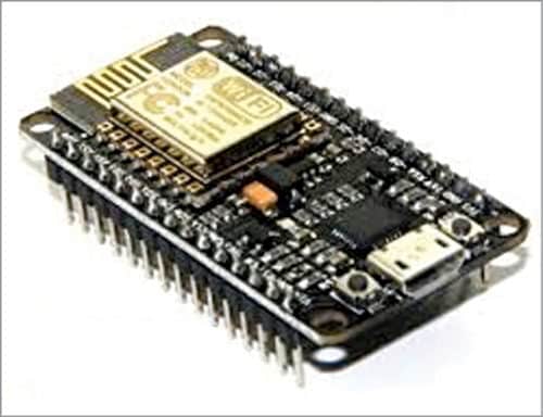
The heart of the IoT system is NodeMCU ESP32/8266 Wi-Fi module. Data pin D8 of IC2 is connected to pin D0 of NodeMCUmodule (Board1) to provide the motor on/off status on a remote computer or smartphone over cloud. Adafruit IoT platform is used to monitor the water-pump’s status online.
Pump’s switching off
When soil is adequately wet, SS1 output pin D0 is low, which makes transistor T1 to stop conduction. So, collector voltage of T1 becomes high (5V), which is connected to pin AD8 of IC1. Transmitter TX1 transmits this signal, which is received by receiver RX1, decoded, and passed on to transistor T2 through resistor R10. So, T2 conducts making its collector low, which turns transistor T3 off. This de-energises relay RL1 and the pump connected to it is switched off.
Pump’s switching on
When soil is dry, SS1 output pin D0 is high, which makes transistor T1 to conduct. So, collector voltage of T1 becomes low (0V), which is connected to pin AD8 of IC1.
Transmitter TX1 transmits this signal, which is received by receiver RX1, decoded, and passed on to transistor T2. This makes transistor T3 to conduct and energise relay RL1, making the pump switch on.
Adafruit IoT platform
NodeMCU Wi-Fi is connected to Adafruit.io open source cloud service to provide real-time data online. Steps to organise the dashboard on Adafruit.io IoT platform are:
1. Open https://io.adafruit.com website. Create an account with a unique username. Note down this username as it will be used in Arduino code (program_soil.ino) later.
2. Generate a key and note down this key. This is a long, unique identifier that you use to authenticate any device using your account. You get one key per account, but you can revoke and regenerate your key any time.
3. After creating an account, you need to manage your feeds for publishing on the dashboard. (Feeds is basically a set of data that you can read or write, as specified in the program, as per your application.) In this project, we used Relay1 on the dashboard, as shown in Figs 6 and 7.


More details regarding configuration with Adafruit IoT and NodeMCU are given in ‘Interfacing with Adafruit and NodeMCU’ document file in the source code folder.
Software
Arduino IDE is used for programming the NodeMCU board (Board1). The Arduino code ‘program_soil.ino’ is to be uploaded into NodeMCU board before connecting it to the receiver circuit.
Connect the NodeMCU to PC/laptop and select proper COM port and board name from Tools menu of the Arduino IDE. The board name we used in this project is ‘NodeMCU 1.0 ESP-12E Module.’ The board name will depend on the model you are using.
Before compiling and uploading the source code, do not forget to include ESP8266WiFi.h, Adafruit, and MQTT libraries from Library Manager. Also, you need to add the ‘package_esp8266com_index.json’ package under Preferences in your Arduino IDE, as shown in Fig. 8.

Next, open program_soil.ino code from Arduino IDE and make some changes, such as Wifi SSID, password, Adafruit username, and key with your own credentials, as shown in the code below:
#include
#include
#include “Adafruit_MQTT.h”
#include “Adafruit_MQTT_Client.h”
#define S0 D0
#define WLAN_SSID “Samsungi” //
**Your wifi name ssid** change it(1)
#define WLAN_PASS “abcd123456” //
**Your WIFI password*** change it(2)
#define aio_server “io.adafruit.com”
//adafruit server
#define AIO_SERVERPORT 1883
#define aio_username “jitendra41085”
//** adafruit username** change it (3)
#define aio_key
“859813f4cb144ee5b0f9e124a239a3f4”
//**adafruit auth key**change it (4)
wificlient client;
Adafruit_MQTT_Client mqtt(&client, AIO_
SERVER, AIO_SERVERPORT, AIO_USERNAME,
AIO_KEY);
Adafruit_MQTT_Publish photocel3 =
Adafruit_MQTT_Publish(&mqtt, AIO_
USERNAME “/feeds/
Relay1”);
void MQTT_connect();
void setup(void)
Now, compile and upload the source code to the NodeMCU board by clicking on the Upload button.
Download Source Code
Construction and testing
An actual-size PCB layout for the transmitter is shown in Fig. 9 and its components layout in Fig. 10. After assembling the circuit on PCB, connect 5V supply across CON1.


An actual-size PCB layout for receiver is shown in Fig. 11 and its components layout in Fig. 12. After assembling the circuit on PCB, connect another 5V supply across CON3. Use a 5V, 10A contact-rating relay for RL1. As relay RL1 is not PCB-mounted, connect its coil to the PCB where it is marked RL1. Connect the water-pump’s power on/off switch across Pole and NO contacts of the relay.
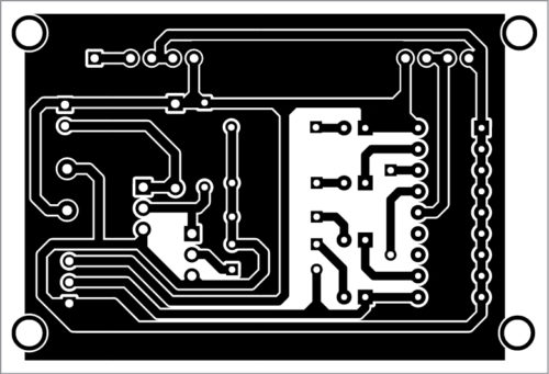

Download PCB and Component Layout PDFs: click here
Switch on the transmitter and receiver circuits. Login to https://io.adafruit.com and open the dashboard you have already created. Depending on the soil moisture level in the field, you will see the relay status on the dashboard, as shown in Figs 6 and 7. When Relay1 status is 1, motor is on and when Relay1 status is 0, motor is off. The status of the relay will change automatically depending on the soil moisture level in the field.
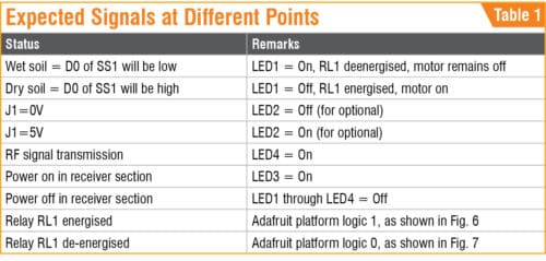
For testing/checking the signals
in transmitter and receiver circuits (Fig. 2 and Fig. 3), the expected signals at different points are listed in Table 1.
Jitendra Jangir is training officer (Electronics) at National Skill Training Institute (W), Patna, Bihar
V.K. Shukla retired as director at Directorate General of Training, Ministry of Skill Development and Entrepreneurship, government of India
Good day! Do you have a direct wireless data transmission project (without internet or other services) between 10 and 15 km? Thank you for your attention
No. We do not have such circuit right now.