![efy test](https://www.electronicsforu.com/wp-contents/uploads/2022/08/efy-tested-1.jpg)
This smart switch for agriculture irrigation system comprises an Arduino board with a GSM module that is remotely controlled by a smartphone. Through this adaptive technology, users can easily monitor the working condition and operational mode of machinery used on their farms from any location, rather than traveling long distances to the field under unfavourable conditions. The main objective is to provide convenience to the farmers.
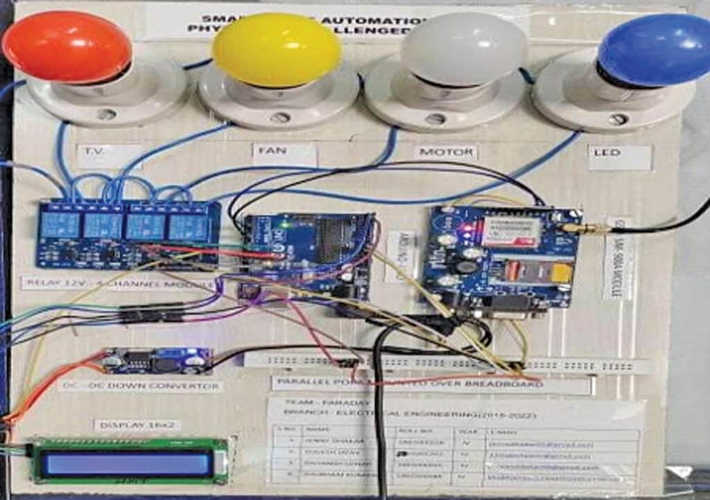
Fig. 1 displays the authors’ prototype on a breadboard. The components required to build this system are listed in the Bill of Materials table.
Also Check: Smart Agriculture Irrigation System
![Smart Switch for Agriculture Irrigation](https://www.electronicsforu.com/wp-contents/uploads/2024/06/Author-Prototype-1-1024x722.jpg)
Smart Switch for Agriculture Irrigation – Circuit and Working
The circuit diagram of the smart switch for agricultural irrigation is shown in Fig. 2. As shown, the switch is constructed around a 50-watt solar panel, a solar charge controller, Arduino Uno board, GSM with GPRS Sim800l module, 16×2 LCD display, four-channel relay module, and a few other components.
![Circuit Diagram of Smart Switch for Agriculture Irrigation](https://www.electronicsforu.com/wp-contents/uploads/2024/06/Circuit-Diagram-1024x638.jpg)
Once the components are connected according to the circuit diagram, the entire device can be powered with the solar panel, and the DC-DC converter converts the voltage to the device’s voltage range. The smart switch system operates using Arduino Uno, GSM module, and a smartphone.
Bill of Materials | ||
Components | Description | Quantity |
Arduino Uno/Nano (MOD1) | 7V-12V | 1 |
GSM with GPRS Sim800l (MOD2) | 5V | 1 |
Four-channel relay module | 5V | Depends on machineries |
DC-DC down converter | 2V to 35V | 1 |
LCD display (16×2) | 5V | 1 |
Inter-integrated circuit (I2C) | 5V | 1 |
Contactors | 200V to 600V | Depends on machineries |
Connecting wires | — | — |
Solar panel | 50W | 1 |
Solar charge controller | 12V | 1 |
The aim of this system is to control different agricultural machinery using a smartphone. When the power is turned on, the connection LED on the GSM module starts blinking. To initiate control, one needs to launch the app (developed through MIT app inventor) on the smartphone and connect to the GSM module. Upon successful pairing, the LED’s blinking stabilises.
![Arduino Code of Smart Switch for Agriculture Irrigation](https://www.electronicsforu.com/wp-contents/uploads/2024/06/Code-snippet-setting-of-the-baud-rate-display-address.jpg)
In the app, different keys are set to transmit different loads and their corresponding values. When a key is pressed on the smartphone, the GSM module receives the corresponding data and internally transmits it to Arduino.
For instance, if ‘motor on’ is sent, the data is transmitted to Arduino, which compares it with the predefined data in the sketch and activates the ‘motor on’ accordingly. This action is applicable to other keys and loads as well.
The code is developed using the Arduino IDE. The Liquid Crystal I2C library is utilised in the code; one needs to install the library using the library manager. Then, configure the I2C display address and display size in the code; here, the project uses 16×2, so that setting is applied.
Software serial pin and baud rate need to be configured in the code. The default baud rate of the SIM800l GSM module is 9600, which is utilised here.
Construction and Testing
Assemble the circuit on a general-purpose PCB or a breadboard. After assembly, enclose it in a suitable casing.
Before assembly, upload the source code into the Arduino Uno board. Insert the SIM card with a message pack into the GSM module. Power the device and wait until the GSM module connects to the network.
Now, one can send messages like ‘Switch2 off’ or ‘all on’ (commands as set in the code) to the device and control the AC motor, pump, or other devices connected to the relay module.
Prof. Latif Khan (left), PhD (purs.), M.Tech (VLSI), BE (ECE), Diploma (Electronics), is Assistant Professor (ECE) and Head, while Yogesh Kumar Jatav (right), B.Tech (Electrical), Diploma (Electrical), is Design Engineer in the Innovation and Incubation Cell at Geetanjali Institute of Technical Studies, Udaipur