Differential drive is used to turn the vehicle left or right depending on the data received from the sensors. Torque values for the controller vary between -255 and +255. Different speeds were tested for the two motors in order to optimise the degree of curve to which the vehicle has to turn in order to avoid obstacles and stay within the lane. The table shows a sample of values that were tested on the motors and their upshots.
Mechanical design overview
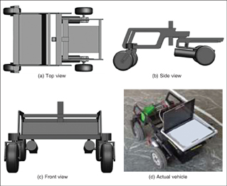
The split-frame design ensures better locomotion capabilities of the vehicle. The front wheels are independent and can rotate 360 degrees. This enables the vehicle to turn sharply when it gets very close to any obstacle.

The design also permits the UGV to negotiate ramps in a better way. The split-frame technology enables independent motion of the two frames and hence the ramp climbing becomes easier, reducing the burden on the motors. Even if one of the four wheels gets stuck in a pothole, the technology ensures that the other three wheels are placed on the ground. This helps the UGV to negotiate uneven surfaces and hence the use of the encoder is evaded.
The design is done on SolidWorks. The UGV is fabricated using mild steel material and is designed to take 150kg load. The material are laser-cut and welded together and then the painting is carried out (refer Fig. 2).
Electrical design
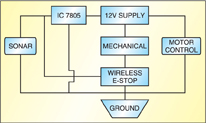
Block diagram of the UGV’s electrical system design is shown in Fig. 3. All the components have a common ground. For safety, emergency stops (E-stops) are connected in series with the circuit. These disconnect the power supply to the circuit with a single push of a button.
The central custom-made power distribution board is made of wood as it has electrical insulating property. Two metallic terminals are firmly mounted on the board and connected to a 12V, 34Ah power source. This connection is made using 40A, thick copper wires. Solar cells are used to recharge the battery.
[stextbox id=”info” caption=”Sample Values Tested on the Motors and Their Upshots”]Left motor Right motor Upshot
@0ST120 @0ST120 Both motors off
@0ST130 @0ST130 Low voltage, vehicle moves with jitter
motion, not stable
@0ST170 @0ST170 Vehicle moves straight smoothly at
average speed of 2 Mph
@0ST170 @0ST140 Vehicle moves right at an angle
@0ST140 @0ST170 Vehicle moves left at an angle[/stextbox]
The other connections from the motors and supply board to the motor controller, mechanical emergency-stop (E-stop) and wireless E-stop are made using 14AWG wires.
Pressing the mechanical E-stop switch turns off the supply to all the components. A normally-closed
(N/C) switch by default, the mechanical E-stop is placed at the back of the robot at an accessible position.
The wireless E-stop switch has a range of about 2.5 metres (100 feet). It employs an inbuilt relay to switch contacts between normally-closed (N/C) and normally-open (N/O) positions. The receiver takes 5V. When a signal is sent, it switches between N/C and N/O.
Software design
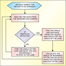
Autonomous challenge algorithm. Team Moksha adopted an ingenious approach for autonomy of the robot. The software design flow-chart is shown in Fig. 4.
Platform. The different devices on the UGV are controlled by a C++ program, which includes an integrated algorithm. The algorithm uses data from the sensing devices, camera, LIDAR and SONAR, and directs the RS160D motor controller. The different devices are connected to the processor using the USB ports, which are interfaced to the devices using USB-to-RS232 converters. This is done since the data is exchanged between the processor and the sensors and motor controller serially.
Image processing. The images are continuously taken from the video captured by a 5-megapixel camera and processed using different image-processing algorithms to detect the lane. This is done using the functions in the OpenCV library. The angle of the lane is calculated using the coordinates of the detected lines from the processed images and the instructions sent to the motor controller to move the UGV in the directed angle.
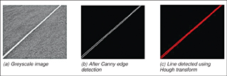
The camera is placed at a height of about 90 cm (3 feet) at an angle facing the ground in front of the vehicle. This is done to avoid detection of any unnecessary line due to noise in the image. Also, proper calibration is done in the program to match the angle of the lane to the angle of the line that appears in the image. The image is processed as follows (refer Fig. 5):
1. First, the RGB image is converted into greyscale.
2. The greyscale image is processed using Canny algorithm to detect the edges.
3. The resulting image is then processed using Hough (Probabilistic) transform to detect only line segments in the image.
Obstacle detection. A serial communication program reads the values continuously from the LIDAR through the serial port. The values are in hex format, which are converted into integer. The protocol structure consists of the following bytes that may be received: start, operation, option (1, 2, 3), scan number, angular step size, start angle, stop angle and distance.
Angular step size specifies the angular separation between two successive transferred measurement values and is equal to 0.36 degree. The difference between start and stop angles gives an approximation about the width of the obstacle. The difference is multiplied by the angular step size to calculate the width of the obstacle. The distance bit is the measured distance of an obstacle from the current location of the LIDAR. Using the distance, start and stop bits, the area around the UGV can be mapped. After knowing the distance and the angle of the obstacle, appropriate commands are given to the motor controllers.
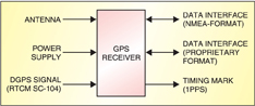
Waypoint navigation. The GPS unit was upgraded to Garmin GPS 18 OEM. It provides non-volatile memory for storage of configuration information, a real-time clock and raw measurement output data in NMEA 0183 format (industry standard).
Each GPS data set is formed in the same way and has the following structure:
$GPDTS, Inf_1,Inf_2,Inf_3,Inf_4,
Inf_5,Inf_6,Inf_n*CS
For example, a GLL data set is shown
below:
$GPGLL,4717.115,N,00833.912,E,130305
.0,A*32
[stextbox id=”info” caption=”Team behind Moksha”]Pavan Kumar P.N. (team leader)
Pramod Bhat M.
Pavan A.
Shashanka U.
Akshay V. Joshi
Arun V.
Anush Zamani
Vishwanath D.
Madhwi Pandey
Rama B.R.[/stextbox]
Data extraction. The UGV employs a Brute force algorithm which relies on the map to navigate. This algorithm evaluates the safest and shortest path to a given location based on cost calculations, which is determined from the frequency of encountering the obstacles. For navigation, the desired location is always a GPS waypoint.
After data extraction, the coordinates are obtained and the destination coordinates fed manually into a sub-controlling program. The program continuously calculates the relative angle between the destination point and the present direction of the vehicle. It decides which point is closest to its present location, selects that point, and then makes its angle calculations using Haversine formula:
a = sin²(Δlat/2) + cos(lat1).cos(lat2).sin²(Δlong/2)
c = 2.atan2(√a, √(1−a))
d = R.c
where ‘R’ is the earth’s radius (mean radius = 6371 km), Δlat = lat2− lat1 and Δlong = long2− long1
This data is returned continuously to the main controlling program where decisions are made. Once the point is reached, the next nearest uncovered point is selected. The process continues till the sixth waypoint is reached.
The GPS receiver returns coordinates, which are converted into decimal degrees. The data input from the GPS software and obstacle-detection sensor is interfaced in the main controlling program. The UGV then finds its way to the waypoints and continues to the next ones. The GPS data is updated continuously.
The author is pursuing BE in electronics and communication from M.S. Ramaiah Institute of Technology, Bengaluru