


In today’s world, most electronic devices are based on embedded systems. From home appliances like microwaves and washing machines to entertainment and security systems, embedded systems have found a way into every field.
What an embedded system is
An embedded system is a computer system with a dedicated function within a large mechanical or electrical system, often with real-time computing constraints. Key characteristics of an embedded system are:
1. Sophisticated functionality
2. Real-time operation
3. Low manufacturing cost
4. Low power

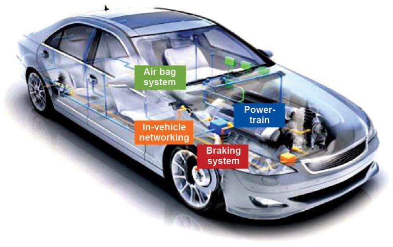
Mechanical systems in automobiles have largely been replaced by electronic systems. Today, the automobile industry is making great use of embedded systems. Ranging from wiper controls to complex anti-lock brake controls and air bags, embedded systems have gained overall control of automobiles.
Automobiles that are built around microcontrollers, digital signal processors or both processors are commonly called electronic control units. Many luxury vehicles have come up with a large number of embedded controllers. The first embedded system based automobile, Volkswagen, came in 1968.
Some current trends of embedded systems in automobiles include air bags, event data recorders, anti-lock brake systems, cruise control, rain-sensing wipers, emission control, traction control, automatic parking, in-vehicle entertainment, back-up collision sensors, navigation systems and tire-pressure monitors.

Airbags

The airbag system is an important safety device that provides extra protection against head-on crash for the passengers, by giving a soft surface to land on. This system works on commands from the airbag control unit, which has a microcontroller. The controller gets power from the battery.
If the collision sensor detects an accident, a signal is sent to the airbag control unit and it is processed by the airbag control unit to determine severity of the impact. If airbag deployment is necessary, the airbag control unit sends a signal to initiate airbag inflators. Inflators are activated through an igniter, causing a chemical reaction that emits nitrogen gas, resulting in the deployment of the airbag cushion.

An occupant detection system is used to determine if a person is seated in the passenger seat and if he or she is of adequate size to be protected in the event of deployment of the passenger seat airbag. It measures the weight of the passenger to determine if the corresponding airbag should deploy.
In 2012-13, a new type of occupant detection system called electrostatic capacitance sensor was implemented. This system does not use weight to determine whether to turn the occupant detection system on or off.
Electrostatic capacitance represents a material’s capability of storing an electrical charge. When someone is seated or when something is placed on the passenger seat, there is a change to that capacitance value. Change in capacitance value is what electrostatic capacitance sensor occupant detection system uses to determine whether the passenger seat airbag will be on or off.
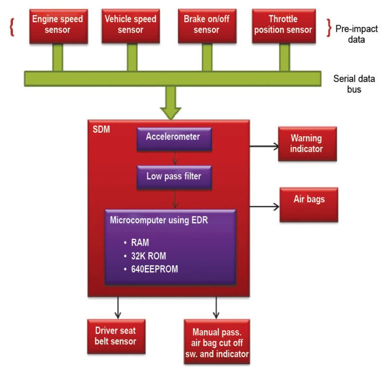
Event data recorder
An event data recorder is a device installed in automobiles to record information related to vehicle crashes or accidents. It is also known as a black box. The sensing and diagnostics module, which is controlled by a microprocessor, has multiple functions, as given below:
1. Determines if a severe enough impact has occurred to warrant deployment of the airbag
2. Monitors the airbag’s components
3. Permanently records information
Event data recorders record a wide range of data, including whether brakes were applied, speed and time of impact, steering angle and whether seat belt circuits were shown as buckled or unbuckled at the time of the crash.
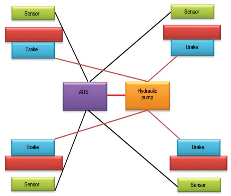
Anti-lock braking system
Up until the 1970s, hitting the brakes too hard could lead to an accident. If the coefficient of slip between tires and the road was too low, hitting the brakes could lead to wheel lock-up. The vehicle would no longer be steerable and would start skidding. The danger is present specially when:
1. Roads are wet and slippery.
2. There are different levels of grip between the tires and the road.
Wheel-speed sensors detect whether a wheel is showing a tendency to lock-up. In case it is, the electronic control unit reduces the braking pressure individually at the wheel concerned. High-speed correction of the braking pressure takes place before the lock-up threshold. The brake-fluid return together with closed-loop brake circuits makes this a safe, reliable and cost-effective system.
An anti-lock brake system is advantageous as:
1. Vehicle remains steerable even during panic braking
2. Shorter stopping distances on all road surfaces
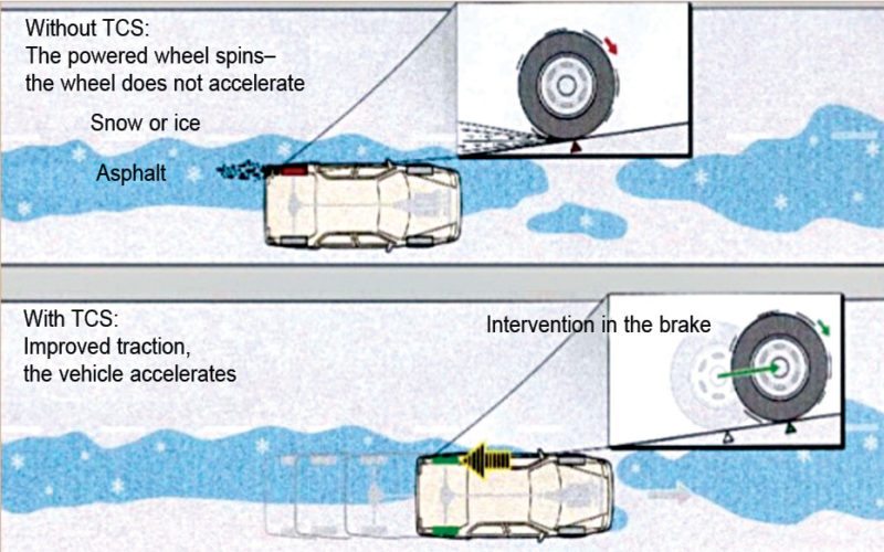
Dynamic traction and stability control
The traction control system is required to prevent driver error from overloading any of the four wheels and causing a slip, through either throttle or brake application. When the drive wheels start losing traction, the dynamic stability control automatically begins stabilisation measures. The dynamic stability control system curbs engine output and stops slips on the wheels. In exceptional situations, however, a small amount of wheel slip can be an advantage.
The principle of the traction control system is the adaptation of wheel torque to the coefficient of friction between the wheel and the road surface.
When the traction control computer detects one or more driven wheels spinning significantly faster than another, it invokes the anti-lock braking system’s electronic control unit to apply brake friction to wheels spinning with lessened traction. Braking action on slipping wheel(s) cause power transfer to wheel axle(s) with traction due to the mechanical action within the differential. All-wheel drive vehicles often have an electronically-controlled coupling system in the transfer case to supply non-slipping wheels with torque.
A traction control system has three main components: a sensor equipped in each wheel that senses changes in speed due to traction, an electronic control unit that receives the sensed speed from each wheel and an automatic traction control valve that supports in braking after the electronic control unit processes information from the wheels.
Embedded navigation system
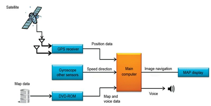
The navigation system consists of an embedded circuitry built with a GPS receiver, gyroscope, DVD-ROM and display system. The GPS receiver receives current longitude and latitude values that are compared with the stored map. The gyroscope and other sensors provide road direction and speed. From all the information gathered at the main controller, the display system displays a navigation or route map of the destination on the display screen.
Embedded rain-sensing system
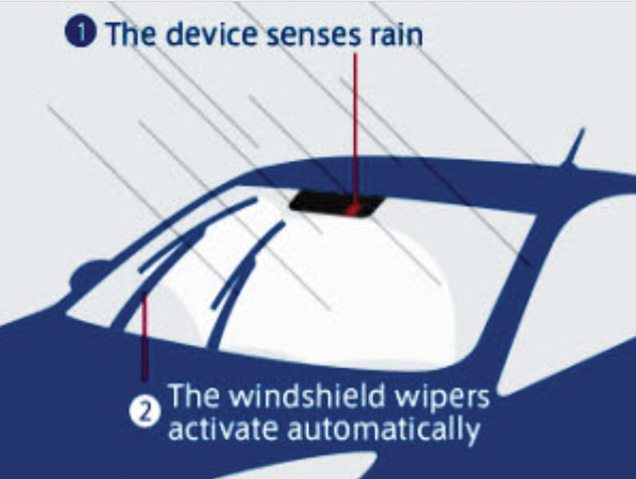
In a rain-sensing system, an optical sensor is placed on a small area on the front windshield glass opposite to the rear-view mirror. This optical sensor emits infrared light and is placed at a 45-degree angle to the windshield. If the glass is dry, most of this light is reflected back into the sensor. If water droplets are on the glass, these reflect light in different directions. The wetter the glass, the lesser the light that makes back to the sensor.
The electronics and software in the sensor turn on the wipers when the amount of light reflected onto the sensor decreases to a preset level. The software sets the speed of the wipers based on how fast the moisture builds up between wipes. It can operate the wipers at any speed. The system adjusts the speed as often as necessary to match with the rate of moisture accumulation.
Embedded based automatic car parking system
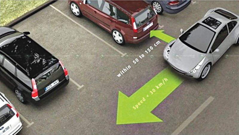
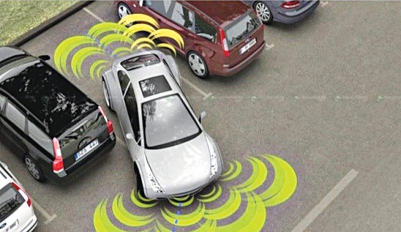
This automatic car parking system is an independent car-manipulation system that moves a car from a traffic lane into a parking spot to perform parallel, perpendicular and angle parking.
The system mainly uses different methods to detect objects around the car. Sensors installed on the front of the vehicle and rear bumpers act as both a transmitter and a receiver. These send a signal that is replicated back when it meets an obstacle near the vehicle and then the car computer receives the time signal and the bumper uses the radar to decide the position of the obstacle. The car senses the parking space and distance from the side of the road and helps the driver drive the car into the parking place.
Future prospects
With the ever-increasing use of embedded systems in automobiles, new technologies and enhancements are being developed to increase usability.
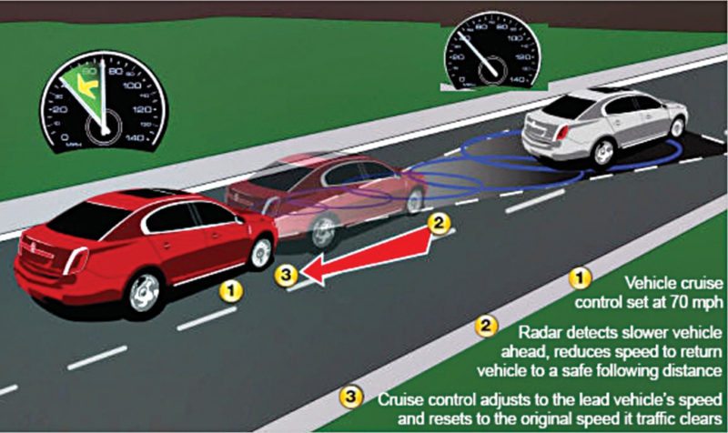
Intelligent adaptive cruise control.
By using this technology we can make driverless vehicle control a reality. Many automobile manufacturers are already engaged with this concept. This adaptive cruise control allows cars to keep safe distances from other vehicles on busy highways. The driver of the car can set the speed of the vehicle and the distance between his car and other vehicles. When traffic slows down, adaptive cruise control changes vehicle speed using moderate braking.
Each car has a laser transceiver or a microwave radar unit, which is fixed in front of the car to find out the speed and distance of the any other vehicle in the pathway. This works on the principle of Doppler Effect, which is basically change in the frequency of waves. It uses a forward-facing radar, installed behind the grill of a vehicle, to detect the speed and the vehicle ahead of it. It can automatically adjust speed in order to maintain proper distance between vehicles in the same lane.
It is hard to implement this system around a curve, when there are elevation changes, during cut-ins, during dense traffic and other situations.
Drive by wire.
Drive by wire system replaces mechanical connections like push rods, rack and pinion, steering columns, overhead cams and cables by mechatronic connections like sensors, actuators, embedded microprocessors and control software.
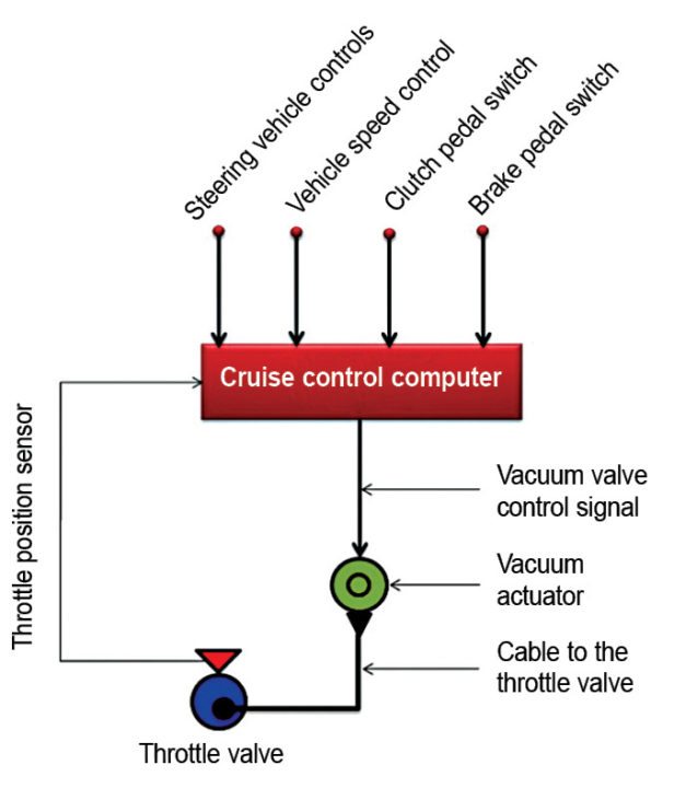
Throttle by wire.
This system helps accomplish vehicle propulsion by means of an electric throttle without any cables from the accelerator pedal to the throttle valve at the engine. It controls electric motors by sensing accelerator pedal input and sending commands to power inverter modules.
Brake by wire.
A pure brake by wire system eliminates the need for hydraulics completely by using motors to actuate calipers and lock the wheels in comparison to the current technology where the system is designed to provide braking effort by building hydraulic pressure in brake lines.
Shift by wire.
Direction of motion of the vehicle (forward or reverse) is set by commanding the actuators inside the transmission through electronic commands based on current input from the driver (park, reverse, neutral or drive).
Steer by wire.
This system provides steering control of a car with fewer mechanical components/linkages between the steering wheel and the wheels. Control of the wheels’ direction is established through electric motor(s), which are actuated by electronic control units monitoring steering wheel inputs from the driver.
Akul Sabharwal is an electronics and communication engineer. He is currently working as R&D head at Sammi Electronics India Pvt Ltd