


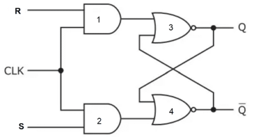
This is the most common flip-flop in electronics. This simple flip-flop circuit has a set input (S) and a reset input (R). Apart from this, you can see the clock at the input end. At the output end, you will find two complementary outputs. The output is also feedback to the input visible in its circuit. Hence Q and Q’ are not the actual outputs.
You can make this simple flip flop either using AND and NOR gates or just NAND gates. We have taken the basic circuit of SR flip flop using AND and NOR gates for better understanding. You can check the logic gate basics.

Let us take a look at the possible cases and write it down in our truth table. The clock is always 1.
SR Flip Flop Working
Case 1: S=0, R=0
Gate1 = 0, Gate2 = 0, Gate3/Q(n+1) = Q, Gate4/Q(n+1)’ = Q’
Note: Since one input of both gate3 and gate4 is 0 and both the gates are NOR gates the output of both the gates will complement the second input as per the property of NOR gates.
Case 2: S=0, R=1
Gate1 = 1, Gate2 = 0, Gate3/Q(n+1) = 0, Gate4/Q(n+1)’ = 1
Note: Since one input of gate3 is 1 and gate3 is a NOR gate, output gate3 will be 0 irrespective of other input as per the property of NOR gate.
Case 3: S=1, R=0
Gate1 = 0, Gate2 = 1, Gate4/Q(n+1)’ = 0, Gate3/Q(n+1) = 1
Note: Since one input of gate4 is 1 and gate4 is a NOR gate, output gate4 will be 0 irrespective of other input as per the property of NOR gate.
Case 4: S=1, R=1
Gate1 = 1, Gate2 = 1, Gate4/Q(n+1)’ = 0, Gate3/Q(n+1) = 0
Note:
- Since one input of gate3 and gate4 is 1 and both the gates are NOR gates, output gate3, and gate4 will be 0 irrespective of other input as per the property of NOR gate.
- Q(n+1) and Q(n+1)’ are complementary outputs hence can’t be the same
- State invalid
Now let us write the truth table-
SR Flip-Flop Truth Table
| S | R | Q(n+1) | State |
| 0 | 0 | Qn | No change |
| 0 | 1 | 0 | RESET |
| 1 | 0 | 1 | SET |
| 1 | 1 | x | INVALID |
We will use this truth table to write the characteristics table for the SR flip-flop. In the truth table, you can see there are two inputs S and R, and one output Q(n+1). But in the characteristics table, you will see there are three inputs S, R, and Qn, and one output Q(n+1).
From the logic diagram above, it is clear that Qn and Qn’ are two complementary outputs that also act as inputs for Gate3 and Gate4, hence we will consider Qn i.e the present state of Flip flop as input, and Q(n+1) i.e. the next state as output.
After writing the characteristic table we will draw a 3-variable K-map to derive the characteristic equation.
Characteristic Table
| S | R | Qn | Q(n+1) |
| 0 | 0 | 0 | 0 |
| 0 | 0 | 1 | 1 |
| 0 | 1 | 0 | 0 |
| 0 | 1 | 1 | 0 |
| 1 | 0 | 0 | 1 |
| 1 | 0 | 1 | 1 |
| 1 | 1 | 0 | X |
| 1 | 1 | 1 | X |
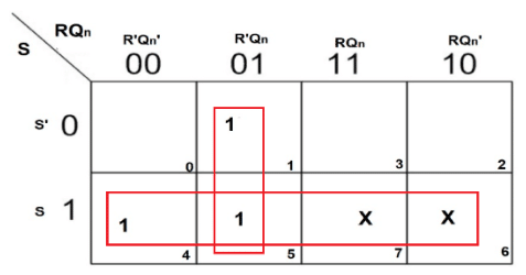
From the K-map you get 2 pairs. On solving both we get the following characteristic equation:
Q(n+1) = S + R’Qn
SR Flip-Flop Advantages
There are several advantages to using an SR flip-flop. Some of them are listed below:
- Simplicity: The SR flip-flop is a simple and easy-to-understand circuit.
- Speed: The SR flip-flop is relatively fast, which makes it suitable for use in high-speed digital systems.
- Low power consumption: The SR flip-flop consumes very little power, which makes it suitable for use in battery-powered devices.
- Bi-stable operation: The SR flip-flop can be set and reset, making it a bi-stable circuit that can hold a state indefinitely until it is changed by an input signal.
Limitations of SR Flip Flop
Apart from several advantages, there are some limitations associated with SR flip-flops. Some of them are listed below:
- Race condition: The SR flip-flop is susceptible to race conditions, which occur when the output state changes unpredictably due to variations in the timing of input signals.
- Invalid states: If both the set and reset inputs are activated at the same time, the SR flip-flop can enter an invalid state where both outputs are high, or both are low. This can lead to unpredictable behaviour in digital systems.
- Limited scalability: The SR flip-flop can be difficult to scale up to more complex digital systems, as it can lead to increased complexity and the potential for errors.
SR Flip-Flop Applications
Some of the applications of SR flip-flop in real-world includes:
- Control systems: The SR flip-flop is used in control systems to synchronize signals and coordinate the operation of other components in the system. For example, in a traffic light control system.
- Memory storage: The SR flip-flop is used in memory storage devices such as registers, which are used to store data temporarily. Registers are used in a wide range of applications, including microprocessors, digital signal processors, and other digital circuits.
- Digital counters: The SR flip-flop can be used in digital counters to count up or down based on an input signal. For example, a timer circuit.
- Data synchronization: The SR flip-flop can be used to synchronize data signals between two digital circuits, ensuring that they are operating on the same clock cycle. This is useful in communication systems where data needs to be transmitted and received at specific times.
- Oscillators: The SR flip-flop can be used in conjunction with other components to create simple oscillators that generate a periodic signal. This is useful in applications such as clock circuits and audio signal generators.