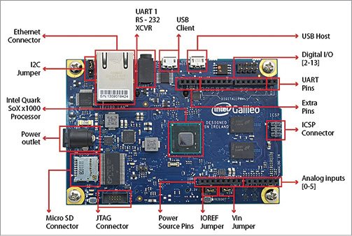
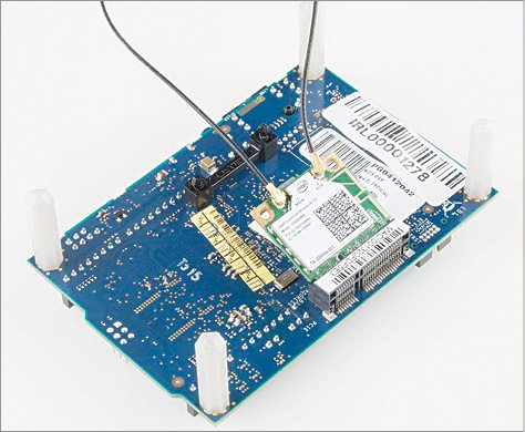
Intel Galileo is a part of Arduino family and is as simple to program even for non-programmers. Arduino philosophy is consistent in Intel Galileo as well. In this article, we shall start with Intel Galileo and then will be able to run our first program. Some more examples like glowing a single LED, multiple LEDs, RGB LED and reading a potentiometer are also presented at the end to help you get hands-on with Galileo board. Intel Galileo board used in this article is shown in Fig. 1 and top view of the board is shown in Fig. 2.

Board interface

Following is the brief description of the components and interfaces of Galileo board:

5V power supply. A 2.1mm centre-positive jack for 5V regulated DC supply is used. Galileo board comes with AC-to-DC power adaptor having an output of 5V, 3A. Voltage input to Galileo board must not be more than 5V.
Ethernet interface. There is one 10Mbps/100Mbps Ethernet interface on board. Ethernet control has a dedicated PHY.

RS232 interface. A 3-pin, 3.5mm jack (audio type) forms the RS232 interface. Ring of the jack is transmitter (TX), tip is receiver (RX) and the sleeve is ground.
USB 2.0 client. To program Galileo board, this port is connected to the computer.
USB 2.0 host. USB2.0 full host supports USB device interface. Up to 128 devices can be connected to this port with the help of a USB device hub.
Arduino interface. There are two interfaces, namely, digital and analogue.
Digital interface. Galileo has 14 digital input/output pins. This includes UART on pins 0 and 1, I2C pins and SPI pins. Six digital inputs/outputs can be configured as PWM (pins 3, 5, 6 and 9-11).
Analogue interface. It has six analogue inputs (A0-A5). It also has an 8-pin power header that includes 3.3V, 5V, GND and reset pins.
Reboot button. Use this button to reboot Galileo board (including Linux). The system will boot back in around 30 seconds.
Pin 13 LED. This is the LED that we will blink during blink test program.
Arduino sketch reset. This is the reset button that will restart Arduino sketch running in Galileo.
µSD card. It has a micro-SD card slot (compatible up to 32GB micro-SD card) and has an inbuilt dedicated SD controller.
PCIe connector. It has a Full PCI Express mini-card slot with PCIe 2.0 compliant features for Wi-Fi, Bluetooth or mobile connectivity; for Wi-Fi, Intel recommends Intel Centrino N135 mini PCIe wireless module as shown in Fig. 3.
Powering up Intel Galileo
To switch on the board and upload the code, the following components will be required:
Power supply. You can use any supply but make sure that it can keep up to 3A, and output voltage must be regulated to 5V DC. Connect the supply to the 5V input connector.
USB to A/B micro cable. This is included with the board. It is used to connect Galileo board to the computer.
Software for Intel Galileo
Standard Arduino integrated development environment (IDE) does not support Intel Galileo.
The supported IDE can be downloaded from communities.intel.com/docs/DOC-22226
Download the version that is compatible to your operating system (OS). The versions available are for Windows, Linux (32- and 64-bit versions) and Mac OSes.
Lab note. This project was tested on Windows 7 and Ubuntu 13.04.
Software installation for Windows

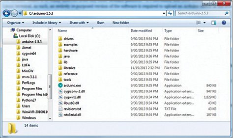
Save the unzipped file in C: drive. The unzipped file can be saved by the same name (Arduino-1.5.3) as shown in Fig. 4.
Open Arduino-1.5.3 folder and run arduino.exe to launch Intel Arduino IDE for Galileo.
After software/IDE installation, connect the board to the computer for which you also need to install required drivers.
Connect regulated 5V supply to Galileo and then connect Galileo to the computer via USB cable only when the LED for USB client turns on. As you connect the board you will receive an error message, that there was some problem in installing the driver as shown in Fig. 5.
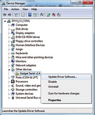
Open Device Manager by clicking Start→Control Panel→Systems→ Device Manager options. Under Other Devices you should see Gadget Serial v2.4. Update the driver from the option as shown in Fig. 6.
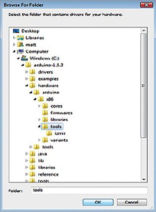
On the first pop-up window, click Browse my computer for driver software. Then, click Browse for the file location path. If you have installed Arduino in C: root drive, then browse the location to C:\arduino-1.5.3\hardware\arduino\x86\tools and click OK as shown in Fig. 7.
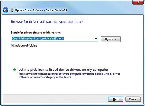
After selecting the driver, click Next as shown in Fig. 8. On Windows security alert pop-up window, click Install.
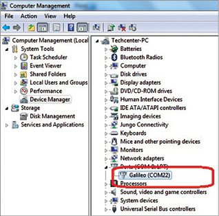
After installation is complete, open Device Manager and locate Galileo com port under Ports (COM & LPT) option as shown in Fig. 9. Note the COM port number; you will need it while uploading software on Galileo.
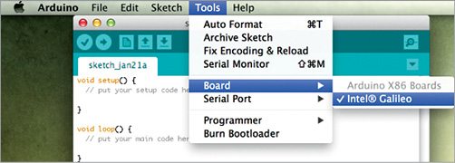
Open Arduino IDE and select Tools→Board. Make sure that Intel Galileo is selected (Fig. 10).
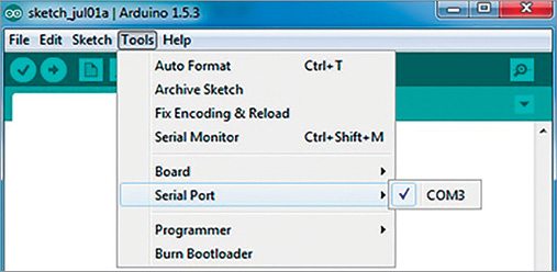
Under Serial Port, select COM port on which Galileo board is connected (Fig. 11).
Software installation on Linux
Arduino software for Linux is in .tgz format. To extract the file you will need Tar tool. Before going ahead, remove Modem Manager System Service as it can hinder working with Galileo. Remove it by running the following command on the terminal:
[stextbox id=”grey”]sudo apt-get remove modemmanager[/stextbox]
On the terminal, navigate to the folder in which Arduino IDE is downloaded (in this case, it is in Downloads) and extract the file by running the following commands:
[stextbox id=”grey”]cd~/Downloads
tar -xzf
-C ~/[/stextbox]
Navigate to the extracted file and run Arduino by running the following commands:
[stextbox id=”grey”]cd ~/arduino-1.5.3
sudo ./arduino[/stextbox]
(Arduino has been run as root because sometimes Arduino does not launch properly without root privilege.)
Driver installation. After software installation on the computer is complete, connect the board to the computer and install drivers.
Connect regulated 5V supply to Galileo and then connect Galileo to the computer via a USB cable.
On the terminal run the following command and note down the port of Galileo (in our case it is ACM0):
[stextbox id=”grey”]ls /dev/ttyACM*[/stextbox]
In case you see an error message Java not found, install Java by running the following command:
[stextbox id=”grey”]sudo apt-get install default-jre[/stextbox]
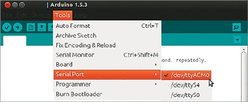
To select Serial Port, go to Tools→Serial Port→/dev/ttyACM0 (Fig. 11).
Software installation on Mac OS
For Mac, unzip the application and save it to the application folder. If you have other Arduino versions, you can save the file by any name, only keep in mind that there should be no spaces in the name. Run the application by double-clicking on it (Fig. 13).
Driver installation. Once software installation is complete, you need to install the driver using the following steps (also shown in Fig. 14):
Connect 5V DC power to the board and then the USB cable (power should always be the first connection on Galileo board).
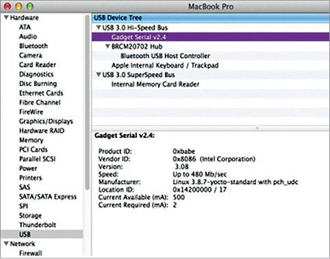
Allow a few seconds for the board to boot up. Open System Information window to check if the board has been detected properly. Path for the same is: Hold Options→Apple menu→System Information. Under USB, check Gadget Serial v2.4 .
Under Network, check the name of your Galileo device; it should be similar to usbmodemxxxx. In this case it is fa21. Note the number as you will need it while uploading the code.
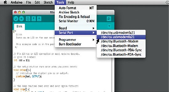
Go to Tools→ Serial Port→/dev/cu.usbmodemfa21 as shown in Fig. 15.
Uploading the code
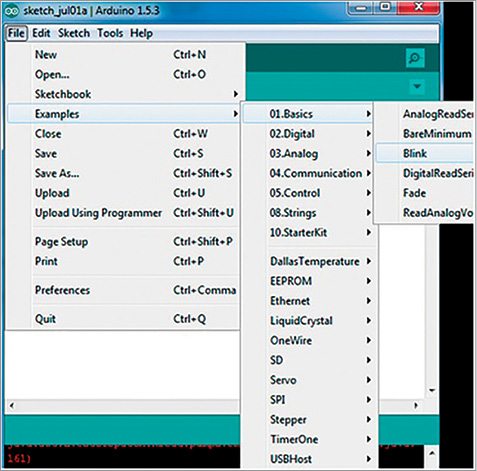
The procedure for uploading Blink example code is the same for Windows, Linux and Mac OSes. To upload Blink example sketch, select the code from the path File→Examples →01.Basics→Blink (Fig. 16).
A new code will open. Click on Upload to upload the code (sketch) on the board. Status of the uploading is displayed on the bottom of the screen (Fig. 17).
When the upload is complete, you will see Transfer Complete message and pin 13 LED blinking on Intel Galileo board.
Some more examples
After successfully running our first LED blinking example, we can proceed to more examples like making LEDs to blink at various speeds, driving multiple LEDs with sequential effects, reading analogue input using simple potentiometer and driving RGB LEDs. So let us begin!
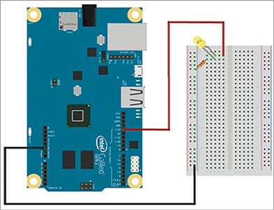
You need a breadboard, resistor, an LED and some jumper wires to set up the hardware. Though the board already has an LED connected to pin 13, we will connect an external LED to feel the experiment. Fritzing software comes handy when you do not have actual components with you. Here, we will use Intel Galileo Gen2 board image in Fritzing environment. (Intel Galileo Gen2 is the upgraded version of Intel Galileo.)
Blinking LED. Wire up the circuit with a 330-ohm resistor using Fritzing as shown in Fig. 18. You can change the blinking speed by varying the delays in blink.ino program.
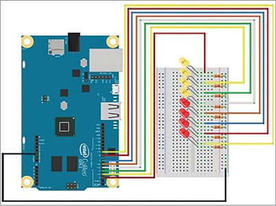
Multiple LEDs. Let us move one step further and connect multiple LEDs. Connect the hardware as shown in Fritzing diagram (Fig. 19). All eight LEDs will turn on/off simultaneously and then create lighting sequences in both right and left directions as defined in sequence.ino code.
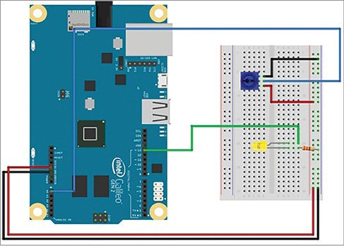
Reading potentiometer. In this experiment, we connect a potentiometer to the board as shown in Fig. 20. The code (potm.ino) reads the resistance values and controls the blinking rate of an LED at pin 13, corresponding to the position of the knob.
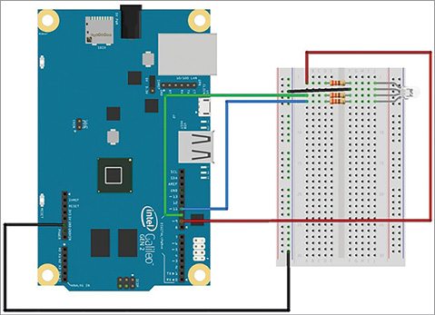
Driving RGB LED. RGB LED is another piece of hardware used here to have some more fun. Connect the hardware as shown in Fig. 21. Once you upload the code, you will see different colours generated from the RGB LED as defined in rgb.ino code.
Krishna Gupta is an electronics hobbyist