


Biomedical electronics, which combines the biological and electronics knowledge, has made appreciable technological progress in recent years. Although implantable bionic systems such as retina and cochlear implants have made remarkable advances, the potential for drug delivery applications has so far remained unrealised.
Historically, drugs were delivered by pills, ointments, injections, etc. In 1964 it was discovered that silicone rubber can be used as drug carrier for low-molecular-weight compounds in animal tissues. This concept was further developed and polymers were used as drug carriers for complex molecules like proteins, polysaccharides and polynucleotides. As a result, more complex drugs, e.g., gene-based drugs, and chimeric antibodies can be delivered to the human body. Today, synthesis and use of polymers has become the dominant approach in drug delivery system.

Generally, drugs contained in the carrier may be released by diffusion or package erosion in the digestive system. This system provides stable release rate, but the release rate is limited and enhancement of release rate requires additional chemicals, e.g., enzymes. Moreover, effectiveness of protein-based drugs can be seriously reduced by the proteases existing in the human digestive system. Although taking drugs through the digestive process may seem less efficient than via injection, it is impractical to ask patients to receive shots repeatedly or visit a clinic every day.

Another drug release approach is a stimuli-released system where the release of drug is triggered by specific stimuli such as electric fields, magnetic fields, enzymes, pH value and temperature change. This approach is very important for protein-based drugs. Because stimuli-controlled drug release does not depend on the dissolving procedure of the package, drugs can be preserved before the stimulus occurs. It prevents proteins from being released too early in the digestive system maintaining their efficiency. However, this system demands that the patients be treated in a hospital.
To resolve the aforesaid issues, an alternative treatment method has been developed recently. This method involves implanting a drug release system in the targeted area on the human body and triggering the drug carrier to release on demand. It envisages fabrication of a drug reservoir directly on the chip with ICs. This goal is achievable with CMOS (complementary metal-oxide semiconductor) compatible deep-trench technology. CMOS device is formed by the combination of PMOS (p-type-channel metal-oxide semiconductor device) and NMOS (n-type-channel metal-oxide semiconductor).

Working principle
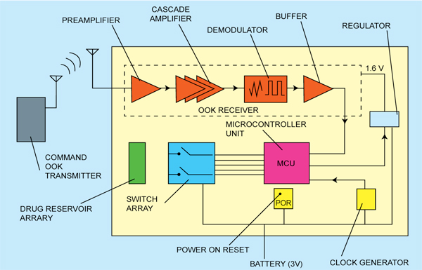
A system-on-a-chip (SoC) with integrated drug reservoirs for drug delivery is shown in Fig. 1. The reservoir structure does not use an alloy as its capping membrane. Instead, it uses the passivation layer already present as a result of the standard CMOS process, which simplifies the post-IC processing procedure. The drug reservoir array is connected with the IC including a system control component and a wireless power circuit. Through these active circuits, the reservoirs may be opened by wireless command, enabling the number of reservoirs opened to be precisely controlled.
Electrolysis is used to generate microbubbles, which are employed as a force to open the reservoirs and release the drug. Wireless components, including an on/off keying (OOK) receiver, microcontroller unit, regulator, clock divider and power-on reset, are integrated for remote drug activation. The size of the microchip is about 2.48 mm2 and the power consumption is 7.57 mW.
System architecture
The architecture of the drug-delivery SoC is shown in Fig. 2. A formatted data stream is modulated by the OOK receiver and transmitted by a transmitter outside the body. The SoC implanted in the patient’s body detects the wireless signal and demodulates it using an envelope detector. Demodulation by envelope detection significantly simplifies the system architecture and reduces power consumption as it does not require any frequency translation.
The demodulated signal is further sent to a microcontroller unit (MCU) for decoding. The decoded information contains the address of the reservoir to be opened up, so that the MCU can direct current into the electrodes of the appointed reservoir.
When the current is ‘on,’ the electrodes begin to generate microbubbles in the solution, which accumulate inside the sealed reservoir until the capping membrane is broken by the gas pressure. The power-on-reset regulator resets voltages of the MCU’s registers at the system start-up before residual voltages result in incorrect system behaviours. The regulator generates a stable supply voltage for the OOK receiver, while the clock generator is used to provide two different clocks for the MCU.
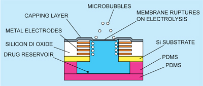
Cross-sectional view of a single unit of drug delivery system is shown in Fig. 3. The passivation layer formed by standard CMOS process is used as the membrane capping for the reservoir, which is opened up by the electrolysis approach.
As shown in Fig. 1, the drug-delivery chip is mounted on board. The PCB is further stacked on a Li-ion nanowire battery, which has high-density charge storage and is rechargeable. A planar inductor on the bottom of the package is used to receive the command signal and the wireless power from command OOK transmitter outside the body. The received power can be stored in the Li-ion battery, for a longer device lifetime. The drug-delivery device is implanted subcutaneously due to signal attenuation in the human body and limited size of the coupling inductor.
Drug reservoir fabrication
The drug-delivery SoC is fabricated by standard CMOS process followed by post-IC processing. After receiving the standard silicon chip with metal electrodes from the foundry, post-IC micromachining is applied to each of the reservoir structures.
First, the standard chip is thinned to 100 μm by mechanical lapping of the substrate. Then photolithography is performed on the back side of the chip to define the positions and sizes of reservoirs. After hard baking the photoresist as the etching blocking layer, the unblock area is trenched by inductively-coupled ion-enhanced plasma etching (ICP) to remove unwanted silicon, enabling formation of drug reservoir. Thereafter, silox vapour wet etching is done to remove the silicon dioxide filled between the electrodes. The electrodes thus exposed are now ready for electrolysis.
After back-side processing, post-IC processing is continued on front side. Passivation etching is done to create a thin capping layer of 200nm thickness in order to decrease the stiffness of the membrane. After this step, reservoirs complete with membrane and electrodes are formed, ready for drug filling.
Cross-section of the integrated reservoir is show in Fig. 3. In order to increase the reservoir volume capacity, a polydimethyl-siloxane (PDMS) layer is bonded on the back side of the chip. Each reservoir is 210 μm long and 110 μm wide.
After PDMS bonding, the reservoirs are filled with the designated drug by an automatic dispenser. A total of eight reservoirs are made with total die size of 1.77×1.4 mm2. By bonding PDMS layer, the capacity of drug reservoir is increased from 5 to 200 nl. Another PDMS film is used to seal the bottom of the reservoir after drug filling. The total thickness of the drug delivery SoC is 0.7 mm. The dose of the drug may be adjusted by controlling the number of opened reservoirs. The reservoirs are designed to be opened up one at a time according to the received command.
On-chip electrolysis
The releasing mechanism of the system is based on electrolysis. The metal electrodes are immersed in the aqueous solution of drug. By injecting currents from the lithium-ion battery, microbubbles of oxygen and hydrogen are generated due to the electrolysis reaction given below:
Anode: 2H2O→4H++4e–+O2 (gas)
Cathode: 2H2O+2e–→2OH–+H2 (gas)
Gases accumulate against the capping membrane until the membrane exceeds its rupture value (about 65 kPa)—a value when the membrane begins to rupture. Once the membrane ruptures, the drug is released. The lethal volume of air in an adult human is estimated to range from 200 to 300 ml. It is known that air bubbles of less than 30 μl dissolve harmlessly into the circulation. Since the volume of microbubbles generated by the device is about 120 nl—much smaller than 30 μl—the released bubble will not cause any health risk to the patient.
Sub-blocks of SoC
OOK receiver. Full integration and low power consumption are very important. Traditional direct-conversion and superheterodyne receivers consume a large amount of power and occupy a huge space. An alternative approach is adaptation of super-regenerative receiver and enveloped detection. Though this approach consumes less power, off-chip components, e.g., discrete inductor, bulk-acoustic-wave resonator and surface-acoustic-wave filter, occupy a huge space, posing a barrier to full system integration. Hence an envelope detection system based on the OOK receiver is adopted.
The envelope detection system based on the OOK receiver requires no off-chip components and on-chip inductor, enabling a reduction in size to 0.60 mm2. The OOK receiver comprises a low-voltage amplifier, an envelope detector and a comparator with an output buffer as shown in Fig. 2. A simple self-biasing technique and envelope detection take place in this circuit. Neither a frequency synthesiser nor biasing circuits are required. The carrier frequency centered at 402 MHz is designed to comply with the medical implant communication system regulation for data transmission and reception in the body.
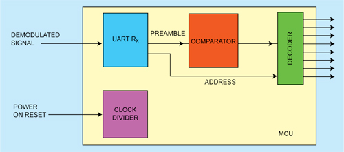
MCU. The function of the MCU is simplified to the basic requirements, i.e., register number recognition release command check and switch array control. Fig. 4 shows the architecture of the MCU. It consists of a clock divider, a decoder, a comparator and a universal asynchronous receiver/transmitter receiver (UART Rx). The UART Rx demodulates the received signal, converts serial bits to a parallel form, and sends the same to the comparator and the decoder for further reaction.
The received command sequence is composed of start/stop bits, address code and a preamble code. The address code is used to specify which branch at the decoder output will be injected with current. The preamble code is used as an activation key sent to a comparator so that the comparator can check the preamble against a default examining code. If these two codes are identical, an enable bit is sent to the decoder and current injection to the designated reservoir initiated according to the address code.
POR circuit. A POR circuit is implemented in the system to reset the register so that the previous values stored in the MCU registers do not activate drug release by mistake.
Regulator. The OOK receiver (1.8V) is biased by a voltage regulator, whereas the other sub-units of the SoC are directly biased by the battery. Controlled by the MCU, the regulator alters its output voltage and switches the receiver between switching mode and quiet mode.
The regulator consists of a startup circuit, a bandgap reference and an error amplifier. The function of the bandgap reference is to generate a temperature-insensitive voltage. A start-up circuit is implemented to prevent the reluctance of the bandgap reference circuit to turn on by the supply voltage. The error amplifier, as a output stage of the regulator, uses a negative feedback to lock its output DC voltage to the reference voltage generated by the bandgap reference, making the output voltage very stable.
At drug-release activation, a DC voltage of 3V is applied to the electrodes, which then conduct a 2mA current into the solution. After activation, microbubbles occur and diffuse from the rupture of the membrane. Only 1.5 mA is needed to open the reservoir after the opening command is given. A Li-ion nanowire battery with an energy density of 7 mA/mm3 and a button cell of 4.5mm diameter and 2mm height (32 cubic mm volume) can provide a total energy of about 403 mWh, enabling the device to power the system for 53 hours. The receiver is turned on for 1 μs every half second to conserve power.
Biocompatibility of the implant is very important. The surface of the device is made of silicon and silicon nitride, while for the packaging material titanium is used. These three materials are biocompatible.