Read part 2
Night vision technology has undergone considerable changes in the last 40 years. These changes have led to enormous improvements in performance standards of night vision devices.
Night vision devices are extensively used by the military for locating enemy targets, surveillance and navigation, thereby playing a crucial role in enhancing their night fighting capability. These are also used by law enforcement and security agencies for surveillance. Night vision-enabled cameras are also being used by both private business houses and military establishments to monitor surroundings of their critical assets.

Various approaches to night vision, their capabilities and limitations, a comparison between the two major categories of night vision devices, namely, image enhancement devices and thermal imaging devices, are presented in this part of the article.
Basic approaches to night vision
Night vision technologies and associated night vision devices enable users to see in low-light conditions. Contemporary devices allow viewing even in near total darkness.
The ability to see in low-light conditions is governed by two basic requirements: sufficient spectral range and sufficient intensity range. Low values of spectral range and intensity range are there in the case of human beings and, so, become the limiting factors for their ability to see with an acceptable level of contrast in low-light conditions. Use of technology to enhance both these parameters makes night vision possible.

Two basic and widely different approaches to night vision include image intensification (or enhancement) and thermal imaging. Both techniques are briefly described in the following paragraphs.
Image intensification
Image intensification or enhancement works on the principle of collecting small quanta of light reflected off the target scene, to be viewed in visible and near infrared (IR) bands of the electromagnetic spectrum in low-light conditions. Collected photons are amplified through the processes of photon-electron conversion, electron multiplication and electron-photon conversion. These processes take shape in an image intensifier tube.
Other important constituent parts of an image intensifier-tube-based night vision device are objective lens for collecting photons, eye piece for viewing the intensified image and power supply for generating required DC voltages for electron acceleration.
Active illumination is often used in conjunction with an image intensifier tube in active night vision technology to enhance the image resolution in very low-light conditions. Illumination is generally provided by IR diodes emitting in the 700nm – 1000nm spectral band.
However, active night vision technology can be detected by night vision goggles and is therefore prone to giving away the location of the user. This is particularly undesirable in tactical military operations.
A variation of the conventional night vision device is the digital night vision device. While in the former, available light is collected through the objective lens and focused on an intensifier, the digital devices process and convert the optical image into an electric signal through a highly sensitive charge-coupled device (CCD) image sensor. This electrical signal is then transferred onto a micro-display, which is a type of LCD flat-panel display screen. The micro-display usually takes the form of an eyepiece, which can be used to view the image, instead of an LCD screen used in most digital cameras.
Digital night vision devices have relatively lower costs, are free from image distortions of photocathodes and blemishes of phosphorescent screen, are immune to damage by bright light exposure and offer image recording facility.
Thermal imaging
Thermal imaging night vision technology works on the principle of detecting the temperature differences between the objects in the foreground and those in the background. All objects above absolute zero temperature emit IR energy. Magnitude of the IR energy emitted by a hot body is proportional to fourth power of its absolute temperature (Stefan-Boltzmann law). Peak emission occurs at a wavelength that is inversely proportional to its absolute temperature (Wien’s displacement law). Therefore hotter the body, higher the magnitude of IR energy emitted by the object and lower the wavelength of peak emission.
A thermal imaging device is essentially a heat sensor capable of detecting tiny differences in the temperature of different points on the surface of the object to be viewed. Information on temperature difference, available in the form of IR energy, is collected by the thermal imaging device and converted into an electronic image. The ability to detect tiny temperature differences that exist not only between the desired object and the surroundings, but also between different points of the object itself, coupled with emission in IR region allows a thermal imaging device to see in near total darkness.
Thermal imaging night vision devices are extensively used not only by military and law enforcement agencies for target detection and acquisition, surveillance and monitoring, search and rescue operations, fire-fighting and so on, these are also used in fields such as medicine, archaeology, process monitoring, automotive industry, meteorology and astronomy.
Image intensifier tube
An image intensifier tube amplifies low-light images to levels that can be seen with the human eye or detected by a digital image sensor. An image intensifier tube collects the existing ambient light originating from natural sources such as starlight or moonlight, or from artificial sources such as streetlights or IR illuminators, through the objective lens of the night vision device.
Low-level light consisting of photons enters the night vision device through the input window and strikes the photocathode. Inside of the input window is generally coated with a thin layer of light-sensitive material. This layer acts as the photocathode, which is protected from any damage from oxidation by operating the image intensifier tube under vacuum of the order of 10–9 to 10–10 torr. Photo electrons released by the photocathode are accelerated and focused by a high magnitude electric field towards the microchannel plate (MCP). The MCP has millions of small channels and the electrons entering these channels are both accelerated by another high magnitude electric field within the MCP and multiplied by secondary emission resulting from electrons bouncing off the inner walls of these channels.
For each electron entering the MCP, approximately 1000 electrons are generated and, subsequently, accelerated from the output of the MCP by a third electrical field towards the phosphor screen. The phosphor screen, which is a thin light-emitting layer deposited on the inside of the output window of the image intensifier tube, converts the impinging electrons back to photons. For every photon entering the input window of the intensifier tube, tens of thousands of photons come out of the output window after emission from the phosphor screen.
This photon multiplication takes place due to electron acceleration in the region between the input window and the photocathode, electron acceleration and secondary emission within the MCP channels, and electron acceleration in the region between the MCP and the phosphor screen. This multi-stage process produces an intensified or amplified image of the object that is much brighter than the original image.
Construction
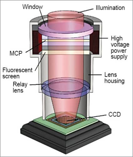
Constituent parts of an image intensifier tube include input window, photocathode, MCP, phosphor screen, output window and power supply. Fig. 1 gives an overview of the constructional features of an image intensifier tube.
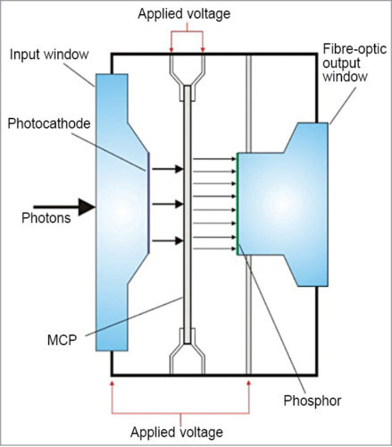
Input window material is selected according to required sensitivity at shorter wavelengths. Common materials used for input window are synthetic silica (transmitting wavelength of 160nm or longer), fibre-optic plate (with transmission wavelength of 350nm or longer), magnesium fluoride (with transmission wavelength of 115nm or longer) and borosilicate glass (with transmission wavelength of 300nm or longer).
The photocathode that converts photons into photo electrons, the MCP that multiplies the photo-generated electrons, the phosphor screen that reconverts the electrons back into photons and the power supply that produces the electric field responsible for acceleration of electrons in different regions are all arranged in close proximity in an evacuated ceramic case.
Efficiency with which the photocathode converts photons into electrons, also known as photocathode radiant sensitivity or quantum efficiency, depends on wavelength. A number of photocathode materials is in use. Of these, gallium arsenide and gallium arsenide phosphide crystals offer extremely high sensitivity. Photo electrons are accelerated by an electric field produced by a high voltage applied between the photocathode and the MCP input surface.
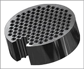
The MCP is a thin glass disk, about 0.5mm thick, consisting of an array of millions of tilted glass channels, each five to six microns in diameter, bundled in parallel (Fig. 2). A single-stage MCP used in second-generation intensifier tubes provides electron multiplication of about 103. Two- and three-stage MCPs produce a gain of 105 and greater than 106. First-generation tubes did not use an MCP.
The number of stages to be used in the MCP depends on the required value of gain. Strip current that flows through the MCP decides the dynamic range or linearity of the image intensifier tube. A low-resistance MCP causing a large strip current to flow through the MCP is desirable for achieving high linearity.
The phosphor screen reconverts the impinging electrons back to photons. Commonly-used phosphor types include P24, P43, P46 and P47. Phosphor screens are characterised by peak emission wavelength, decay time, power efficiency and emission colour.
Phosphor screen decay time is one of the most important parameters to be considered while selecting a suitable phosphor type. The ideal phosphor type is one whose decay time matches the readout method and whose spectral emission matches the readout sensitivity. When used with a linear image sensor or high-speed CCD, a short decay time is recommended for the phosphor screen, to avoid the appearance of an after-image in the next frame. On the other hand, a short decay time that minimises flicker is recommended for night time viewing and surveillance applications.
Output window material is selected to match the readout method. Different output window types include borosilicate glass, fibre-optic plate and twisted fibre-optics.
A borosilicate glass window is used for relay lens readout. In this case, the relay lens is focused on the phosphor screen.
Fibre-optic output plate—a standard output window—is ideal for direct coupling to a CCD with fibre-optic plate input window. It consists of millions to hundreds of millions glass fibres bundled in parallel. A fibre-optic plate can transmit an optical image from one surface to another without causing any distortion. Diameter of the glass fibre matches the channel diameter of the MCP.
Twisted fibre optics as output window are used for night time viewing applications. Twisted fibre optics reduce eyepiece length, thereby making the night vision device more compact.
Image intensifier tube-based night vision devices are made in a variety of package configurations (Fig. 3), according to the requirements of specific application scenarios.
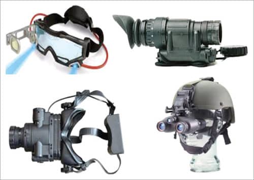
These mainly include night vision monoculars, binoculars, weapon sights and goggles.
Operational modes
There are two common modes of operation of an image intensifier tube: gated and photon counting. In the gated mode of operation, the intensified image can be gated to open or close the optical shutter by varying the potential difference between the photocathode and the inside surface of the MCP, thereby either allowing or disallowing the formation of an intensified image.
In gate-on mode, potential of the photocathode is lower than that of the MCP. As a result, photoelectrons are attracted towards the MCP, to be subsequently multiplied and hit the phosphor screen, producing an intensified image.
In gate-off mode, potential of the inside surface of the MCP is less than that of the photocathode so that photo electrons can revert back to the photocathode. Therefore no intensified image is seen on the phosphor screen.
In practice, MCP potential is fixed, and the intensifier tube is turned on by applying a negative polarity pulse of about 200 volts to the photocathode. Gated operation is very effective in analysing high-speed optical phenomenon.
Image intensifier tubes using a three-stage MCP have much higher sensitivity than those employing a single-stage MCP. This is important when it comes to operating at extremely low-light levels. When the light level is as low as 10–4 lux, a three-stage MCP helps in producing an image of acceptable quality. However, when the light level falls below 10-5 lux, incident photons are separated in time and space.
It is no longer possible to capture an image with a gradation. At extremely low-light levels, when only a few light spots appear on the phosphor screen per second, a good-quality image can be obtained by detecting each spot and its position, and integrating these into an image storage unit. Brightness distribution in photon counting mode is given by the difference in the number of photons at each position.
Different generations of image intensifiers
Night vision technology has undergone substantial changes in the last 40 years. These changes have led to gigantic improvements in performance standards of night vision devices. Each substantial change in technology is associated with a generation. We have seen several generations of night vision devices based on image intensifier tube technology. Beginning with generation-0, we are currently on generation-4.
Generation-0
The earliest night vision devices existed during World War II and the 1950s. These devices were based on image conversion rather than image intensification. The night vision devices primarily comprised a photocathode that converted incident photons into electrons. The electrons were accelerated towards an anode by applying a positive potential to the anode. The devices also had an IR source of radiation, called IR illuminator, mounted on the device. The IR illuminator irradiated the target scene with IR radiation. IR radiation reflecting off the target back to the night vision devices was collected by their objective lens and focused on to the photocathode.
Generation-1
Generation-1 night vision devices were an adaptation of generation-0 technology—both used a photocathode and an anode, the former for photon-to-electron conversion and the latter to accelerate photo electrons towards it. A major deviation in generation-1 devices from generation-0 ones was the absence of an IR source that was used in the case of the latter devices to provide scene illumination.
Generation-2
These vision devices were the first to use an MCP for electron multiplication. This led to significant increase in device sensitivity.
Consequent light amplification was of the order of 20,000x. This resulted in much improved performance even in very low-light level ambient conditions of cloudy and moonless nights.
Introduction of the MCP into the intensifier tube also obviated the need to connect the tubes in series, as was done in generation-1 devices. This significantly reduced the size of the night vision devices, and made handheld devices and helmet-mounted devices a reality.
Generation-3
Compared to generation-2, generation-3 night vision devices have two distinctive changes: use of gallium arsenide photocathode and ion barrier coating on the MCP. Due to its higher quantum efficiency or radiant sensitivity, and its spectral response extending to near IR region, gallium arsenide photocathode enables target detection at longer ranges and in darker conditions.
Light amplification factor increased from 20,000 times in generation-2 devices to a maximum of 50,000 times in generation-3 devices. The ion barrier film improved the tube life from 2000 hours in generation-2 devices to 10,000 in generation-3 devices—even though it was at the cost of slight reduction in radiant sensitivity due to fewer photo electrons being able to reach the MCP.
Generation-3+ devices offer improved performance specifications over generation-3 devices. Two important features associated with generation-3+ night vision devices are an automatic gated power supply system and a thinned ion barrier layer. Absence of the ion barrier layer or its thinning improves luminous sensitivity, even though it is at the cost of a slight reduction in the life of the tube.
Another common term encountered while discussing night vision technology is omnibus, or OMNI. This refers to the multi-year/multi-product contracts of the US Army for the procurement of night vision devices from Exelis (formerly ITT Night Vision). Under these contracts, the company delivers generation-3 devices with increasingly higher performance. Current contract is for OMNI-VIII.
Generation-4
As of now, there is nothing like generation-4 night vision technology. Generation-4 night vision devices were initially conceived to use filmless and gated technology. The proposal was to remove the ion barrier film from the MCP, which was introduced in generation-3 devices. Removal of film was aimed at reducing background noise and enhance signal-to-noise ratio. It would also allow more electrons to reach the MCP, so that images were significantly less distorted and brighter.
Introduction of automatic gated power supply for the photocathode enabled the devices to adapt instantaneously to light level fluctuations from low-light level to high-light level, or from high-light level to low-light level. Removal of the ion barrier was also intended to reduce the halo effect seen around bright spots or light sources. While device performance improved, absence of the ion barrier film led to increased tube failure rates. As a consequence of this, the idea of film removal was abandoned in favour of a thinned film, giving birth to generation-3+ described in the previous section.
Intensified CCD
Intensified CCD, or ICCD, successfully exploits the optical amplification provided by an image intensifier to overcome the limitations of the basic CCD sensor. Two important features of an ICCD are high optical gain and gateable operation. Both attributes are characteristic of the image intensifier tube.
Though image intensifiers were initially developed for the military and law enforcement agencies for a range of deployment scenarios in surveillance, targeting and navigation, development of ICCD technology and devices extended their usage to many a scientific application in spectroscopy, scientific and industrial imaging, and medical diagnostics. In fact, development of image intensifier tubes is increasingly being driven by scientific applications.
Construction
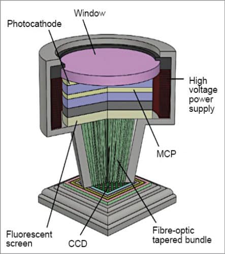
An ICCD primarily comprises an image intensifier tube whose light output is coupled with a CCD sensor. Output of the image intensifier is coupled with the CCD, typically by a fibre-optic coupler (Fig. 4). A fibre-coupled system is physically compact with low optical distortion levels. High efficiency fibre-optic coupling also allows the image intensifier tube to operate at lower gains, which, in turn, results in better dynamic range performance.
A lens-coupled ICCD uses a lens between the output of the image intensifier and the CCD (Fig. 5). Lens coupling offers flexibility of using the ICCD sensor in non-intensified mode by allowing the image intensifier to be removed.
Disadvantages of lens-coupled ICCDs are larger physical size, lower coupling efficiencies and increased scatter. Power supply is another important constituent part of the ICCD sensor. The power supply section generates DC voltage (typically 600 to 900 volts) for the MCP to achieve desired gain, DC voltage (typically 4kV to 8kV) for the phosphor screen and voltage pulses (typically 200 volts) for gated operation of the photocathode.
The gating pulse width and rise/fall time depends on desired gating parameters. Gating pulse width of less than a nanosecond and rise/fall time of a small fraction of a nanosecond are achievable.
Characteristic features
Important characteristic features of an ICCD include spectral response, spatial resolution, gating time and repetition rate, noise, sensitivity, dynamic range and frame rate. The spectral response of an ICCD camera is primarily determined by the input window, photocathode materials and photocathode size used in the image intensifier tube.
The noise and, hence, sensitivity of the ICCD is also governed by the image intensifier. A noise component called dark current component, also known as effective background illumination (EBI), originates from thermally-generated charge in the photocathode. Dark current is generally not an issue when using short gate times.
Spatial resolution is defined as the number of line pairs a camera can resolve per millimetre. Among the several methods available for measuring the resolution of an optical system, modulation transfer function (MTF) is in common use.
Dynamic range of the ICCD is governed by the CCD section and varies inversely with gain of the ICCD. A higher dynamic range CCD used in the ICCD will result in a higher dynamic range ICCD camera. As gain increases, smaller signals that can be accommodated are compensated by the lower read noise to keep the dynamic range constant.
When the read noise drops below a single photon level, dynamic range of the ICCD starts dropping as gain increases further. Frame rates of an ICCD are governed by CCD specifications, especially the number of pixels and pixel readout rate.
Thermal imaging
CCD and CMOS sensors have a spectral response sensitive to the visible region of the electromagnetic spectrum, with the trailing part extending slightly to near IR region.
A thermal imaging sensor, on the other hand, uses focal plane arrays comprising IR sensing elements that respond to mid (3 to 5 microns) and long IR (8 to 14 microns) regions. IR energy radiated by the object to be imaged is incident on the thermal imaging sensor, which uses a series of complex mathematical algorithms to construct the image visible to the viewer. As the thermal imaging sensor does not need visible light for operation, it can see in total darkness.
Thermal imaging sensors are far more expensive than their visible spectrum counterparts. In view of their military applications, high-end devices are often export-restricted.
Operational basics
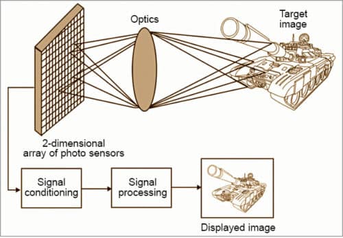
A thermal imaging sensor makes use of thermal radiation emitted by the target or scene of interest to generate its image. Essentially, it comprises front-end optical system, two-dimensional array of IR detector elements and image processing circuitry to produce output in the desired format. The front-end optical system focuses IR radiation emitted by all objects in view on a two-dimensional array of IR detector elements, which create a detailed temperature pattern of it, called a thermogram.
The thermogram is generated from several thousand points in the field-of-view of the detector array. The thermal imager measures very small relative temperature differences and converts otherwise invisible heat patterns into clear, visible images that can be seen through either a viewfinder or a monitor.
Most thermal imaging sensors scan at a rate of 30 times a second. These can sense temperatures in the range of –20°C to +2000°C, and can sense temperature changes as small as 0.1°C. In the next step, temperature pattern is translated into electronic impulses. The signal processing unit converts these electronic impulses into data for the display. Fig. 6 illustrates the concept of thermal imaging.
Types of thermal imaging sensors
There are two distinctive detector technologies: direct detection (or photon counting) and thermal detection. In direct detection, the detector element translates the photons directly into electrons. The charge accumulated, the current flow or the change in conductivity is proportional to the radiance of objects in the scene. Detectors in this category include lead selenide (PbSe), mercury cadmium telluride (HgCdTe), indium antimonide (InSb), platinum silicide (PtSi) and more.
All thermal imaging sensors based on direct detection technology, except those working in short-wave IR (SWIR), use detectors cooled to cryogenic temperatures close to –200°C. Newer photon-type IR sensors operating at elevated temperatures are now available. This has allowed solid-state thermal electric coolers and sterling coolers to be used.
Cooled thermal imagers are highly susceptible to damage from rugged use, have a long cooling time of typically a few minutes, limited MTBF of a few thousand hours, high cost, large size and weight, and high electrical power consumption leading to short battery life. The biggest advantage of these detectors is excellent spatial resolution and sensitivity that results from detector cooling.
Thermal detection, on the other hand, uses uncooled detectors. These make use of secondary effects such as relation between conductivity, capacitance and expansion, and detector temperature. Detectors in this category include bolometers, thermocouples, thermopiles and pyroelectric detectors. These sensors operate at room temperature and are lightweight. This feature, for example, allows microbolometer thermal imagers to be mounted on helmets.
Different generations of thermal imaging sensors
There are different generations of thermal imaging sensors. Each successive generation has incorporated not only a major change in the type of detector but also a major change in optical systems used to image the target onto the detector.
Four distinct generations of thermal imagers have been designed, based on IR detector technologies developed during the last 35 years, and classified according to the number of elements contained in each group. First-generation thermal imagers contain single element detectors, or detectors with only a few elements (1×3). A two-dimensional mechanical scanner was usually used to generate a two-dimensional image.
Sensitivity of thermal imaging sensors of the first generation was limited by background radiation. This problem was overcome in second-generation thermal imaging sensors by using modified front-end optics that reduced unwanted flux. However, this resulted in a fixed f-number for all fields-of-view.
Second-generation thermal imagers are vector detectors, usually containing 64 or more elements. The two-dimensional scanner was somehow simplified in the vertical direction to include only the interlace motion.
Third-generation thermal imagers contain dual-band, two-dimensional arrays with several columns of elements and dual/variable f-number optical system. These thermal imagers still scan in one direction and perform time-delay integration of the signal in the scanning direction to improve signal-to-noise ratio.
Fourth-generation thermal imagers contain two-dimensional array detectors (160×120, 320×240, 680×480) called focal plane arrays that do not require any scanning mechanism for acquiring two-dimensional pictures.
Applications of night vision equipment
Night vision equipment finds extensive usage in a wide range of applications in military, law enforcement, surveillance, security, navigation, hunting, wild life observation and so on. These devices are used not only by the military, police forces and law enforcement agencies for navigation, surveillance and targeting, these are also used by private detectives, fire-fighters, hunters and nature enthusiasts. Both image enhancement and thermal imaging night vision equipment have preferred areas of application to which these are better suited than the other.
Image enhancement night vision devices
Image intensification night vision needs at least a small amount of light to operate. This ambient light, in some cases, may be provided by the moon and stars. In the case of total darkness, the night vision device can see no better than the naked eye. This shortcoming is overcome with the use of an IR illuminator, which works like a flashlight for night vision while staying invisible to the naked eye.
Use of an IR illuminator has a drawback. It makes the device highly prone to be detected by enemy’s night vision device.
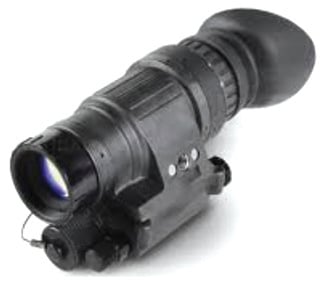
Night vision technology is used extensively by the military and police due to the instant tactical advantage they get through the ability to see in the dark, and precisely detect and even identify the target even from a distance. AN/PVS-14 (Fig. 7) is one such versatile night vision scope extensively used by armed forces and special operations units. It is a monocular night vision device designed for use by the individual soldier in a variety of ground-based night operations. While the dark-adapted unaided eye provides situational awareness and vision of close-range objects, the night vision device provides long-range vision of potential threats and targets, thus, making it a force multiplier in night time warfare.
Night vision cameras are extensively used for surveillance and security applications, especially for around-the-clock surveillance, indoors and in controlled environments. Such cameras provide enhanced security by improving video images in low-light conditions. With the help of IR illumination, these can be effectively used in near total dark conditions, too. Perhaps, the greatest feature of night vision cameras is that these are true 24×7 cameras, as these are the only cameras with the ability to record any event in a protected area around the clock when connected to a digital video recorder.
Night vision cameras are available in two basic styles: dome and bullet. The resolution typically varies from 400 TV lines to 700 TV lines. Security cameras with long-range night vision find extensive usage in monitoring large parking lots, huge and dark warehouses, apartment complexes and other similar assets on 24×7 basis. Traffic monitoring and monitoring of suspicious activity in public places, security installations and critical national assets are other important application areas of security cameras with night vision capability.
Thermal imaging night vision devices
Thermal imaging devices are used on land-based armoured fighting vehicles, naval vessels and aerial platforms such as aircraft, helicopters and missiles for surveillance, target acquisition and tracking applications. Some common non-military applications of these systems include surveillance of living things, search and rescue operations during fire-fighting, detection of gas leaks, monitoring of volcanoes and detection of heat in faulty electrical joints.
In military applications, thermal imaging devices offer several distinct advantages. The first is their immunity to detection by the adversary. These are passive sensors that do not emit any radiation for generation of images.
Second, it is extremely hard to camouflage the target from the sensor as these sense heat radiation.
Third, thermal imagers can see through smoke, fog, haze and other atmospheric obscurants better than sensors operating in the visible spectrum.
One limitation of thermal imaging sensors is that these cannot discriminate between a friend and a foe. Friendly forces can use heat beacons to overcome this shortcoming.
Thermal imagers can be extremely useful in fire-fighting operations. Their ability to see through smoke and debris allows fire-fighters to find people who have passed out and those fighting for survival but are too afraid to come out from hiding. Thermal imagers can also tell a fire-fighter if a door is hot and possibly contains a fierce blaze on the other side.
Thermal imagers designed for fire-fighting missions are designed to operate in very rough and tough environmental conditions.
Thermal imagers are extensively used by law enforcement agencies and armed forces for a variety of applications in navigation, detection and targeting. These allow them to detect potential threats without exposing their location to the adversary. State-of-the-art thermal imaging rifle scopes have become rugged enough to withstand the abuse of recoil, making these extremely popular with the armed forces.
While thermal imagers are incredibly effective when it comes to detecting human beings or animals, discrimination between a friend and a foe may be a challenge. This may be an issue in life-and-death situations.
Thermal imaging cameras are one of the most effective tools for surveillance because these work equally well during the day and at night. Regular CCTV cameras are limited by their need for light, and night vision devices do not function during the day. The chance to see through smoke and fog also gives thermal a leg up on other surveillance techniques.
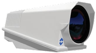
Fig. 8 shows a thermal imaging sensor designed for border and coastal surveillance array. It offers continuous zoom from 25° to 2°, and a long-range detection capability. The sensor can detect a human being-sized target from more than 15 kilometres away.
State-of-the-art sensors intended for surveillance, target detection and tracking applications employ multi-sensor configurations, often combining a visible spectrum sensor with an IR sensor. Final image in this case is the result of fusion of imaging data from two sensors.
To be continued…
Dr Anil Kumar Maini was formerly outstanding scientist and director at Laser Science and Technology Centre (DRDO)
Nakul Maini is post graduate in optical engineering from University of Bristol (UK), currently working as senior engineer (product development) at Tek Xplore, New Delhi