


Automation of the testing process enables manufacturers to check each finished product rapidly and consistently. This also increases speed and overall quality levels.
A system-on-chip (SoC) is essentially an integrated circuit (IC) that takes a single platform and integrates an entire electronic or computer system on a single chip. An SoC helps reduce energy wastage, cost and space occupied by large systems and, hence, power. It has made possible to create a plethora of portable devices that can be carried anywhere.
Application of SoCs in the practical world is limitless and priceless. These chips are frequently used in systems related to the Internet of Things (IoT), embedded systems, smartphones, cars, cameras, tablets and more. SoCs help improve performance by using a single chip to manage the various aspects of the system.
Depending on the kind of system, SoCs can speed up data transmission for a variety of functions including signal processing, wireless communication and artificial intelligence (AI). These can also minimise latency, provided the various elements are strategically placed on the motherboard to minimise interference and interconnection delays.
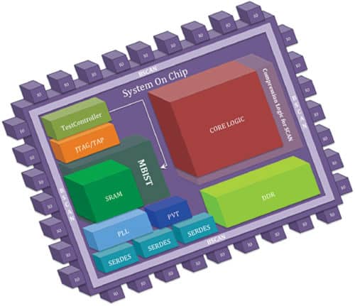
An SoC’s building blocks
An SoC combines the power of the CPU with several other components like input and output ports, internal memory, etc to perform and execute its functions. Components that an SoC generally incorporates within itself include:
- A processor or multiple processors at its core to define its functions. It can be a microcontroller (MCU), a microprocessor, a digital signal processor, an application-specific instruction set processor or field programmable gate array (FPGA).
- Internal memories like RAM, ROM, EEPROM or flash to perform computation.
- External interfaces to comply with such industry-standard communication protocols as USB, Ethernet and HDMI. It can also incorporate wireless technology, and involve protocols of Wi-Fi and Bluetooth.
- A graphical processing unit to help visualise the interface.
- Other necessary components such as voltage regulators, phase lock loop control systems and oscillators, clocks and timers, analogue-to-digital and digital-to-analogue converters, etc.
- An internal interface bus or network to connect all individual blocks.
SoC testing
SoCs enable tight integration of components on a single chip, but this necessitates comprehensive testing of electronic devices before dispatch.
Testing of SoC devices has become an increasingly challenging task as these devices have become extremely complex. SoC chips are constructed block-by-block, so testing is efficient when it is also done block-by-block. Designers can install a specialised, configurable, pre-designed embedded system to test and debug each block. Such an embedded system can specify test speed, diagnostic options, fault coverage and test length while testing any random logic block.
Compared to CPUs, SoCs use shorter wiring and subsequently utilise less power, making them much more efficient and energy-smart. The only problem with SoCs as compared to CPUs is upgradation and repairing. Where you can easily replace and use new components such as RAM or GPU in CPUs, doing so is a much more complicated process with SoCs.
A few major SoC test equipment manufacturers are Advantest Corp., Astronics Corp., CHROMA ATE Inc., Cohu Inc., Teradyne Inc. and Keysight.
Semiconductor automated test equipment (ATE) consists of various instruments or cards used for testing SoC components, both at wafer and packaged stages. These test systems are continuously evolving as per demands in consumer, computing and communication markets. Today’s ATE products must provide more functionality at higher speeds to keep pace with innovation in the semiconductor industry.
Programmable logic plays an indispensable role in ATE product development by providing scalability and flexibility. Such functions as timing accuracy, high-speed I/O capability, digital signal processing (DSP) analysis, memory control and jitter compliance are all taken care of by programmable logic. With increasing complexity of ATE products, more intellectual property (IP) is persistently being integrated within the programmable logic.
In-circuit testing
Manufacture of electronic assemblies involves many complex tasks that are vulnerable to faults. So, the PCB assembly, components on the board and integrity of the parts are tested to ensure that the end-product meets quality and design standards.
In-circuit testing (ICT) is a widely-recognised, cost-effective method to test medium- or high-volume PCBs. It provides more reliable results as it individually tests PCB components one at a time. ICT assists original equipment manufacturers (OEMs) and contract manufacturers to meet defined parameters consistently during the entire production process.
ICT can be performed with a bed-of-nails test fixture or a flying probe setup because of multiple contact pins PCBs contain. In ICT, test signals are transmitted into and out of PCBs at high speed to evaluate circuits and components. During ICT, all components on the PCBs are measured to detect defective components and replaced accordingly. Function tests check the entire intended function of the PCBs.
Benefits of ICT
An ICT fixture can either be vacuum or pressed-down. A vacuum fixture gives better signal reading versus the pressed-down type; although, the former is more expensive due to its high manufacturing complexity. Some other benefits of ICT are:
- ICT takes less time to perform the test. For example, if a flying probe takes twenty minutes or so, ICT for the same test might take a minute or so.
- It checks and detects shorts, opens, solder bridges, missing components, wrong-value components, wrong polarities, all manufacturing defects, design faults and flaws, component failures and current leakages in the circuitry.
- Testing platform is available for most testing needs on Windows as well as UNIX.
- Operating environment and test development interface are based on standards for open system offerings. ICT also enables fast integration into an OEM customer’s existing processes.
- However, a costly fixture is required as ICT covers hundred per cent testing so that all power and ground shorts are detected.
Role of software in ICT
An in-circuit tester can be programmed easily by taking files from the PCB layout to generate much of the required program. To speed up the process of testing, there are different software available that can run required tests on the assembly. Software can be written for each board type to be tested.
The software instructs the test system which tests to perform, at what points, and details of correct and defective component criteria. It runs tests designed to identify any potential problems by measuring electrical parameters, powering on and off certain areas, and flagging any results that indicate an issue.
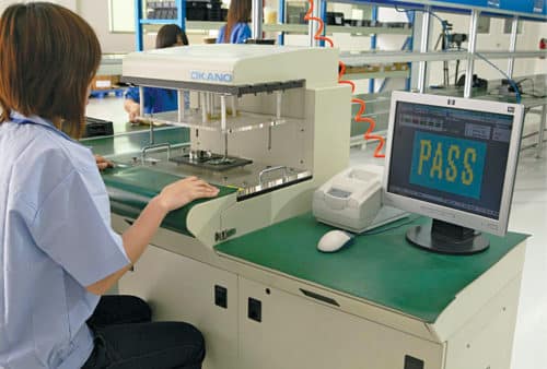
Automation of the testing process enables manufacturers to check each finished product rapidly and consistently. This also increases speed and overall quality levels. Some parameters that the regular ICT setup checks include:
Error detection
A more tightly-populated PCB is more exposed to damage during the assembly process. An ICT detects and isolates any open or short-circuits on the PCB board.
Part placement
An ICT routinely checks for improperly placed or substituted components.
Electrical requirements
It runs the power signal to check voltage levels, resistance and capacitance measurements at different nodes of the board to determine if they meet design specifications.
Component condition
By measuring component reaction at specified voltages and currents, designers can quickly locate and replace damaged components.
Once testing is completed, a report is generated that includes points about tested, partially-tested and untested components, details of fixture wiring and probe types used, and software employed, so that the PCB fabricator can closely analyse the report and make appropriate changes accordingly.