


Once confined to science fiction, space-based solar power is emerging as a technically viable and increasingly economical route to continuous clean electricity generation. But how?
The idea of SMALL CAPS Space-Based Solar Power (SBSP) was first proposed by Russian scientist Konstantin Tsiolkovsky in the 1920s. It was later developed by Dr Peter Glaser of the United States, who conceptualised the modern SBSP system in 1968.
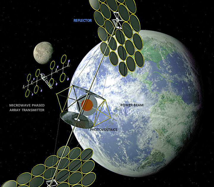
An SBSP system consists of an orbiting satellite, primarily composed of solar panels, that transmits power to a ground-based receiving station via electromagnetic waves. Besides the solar arrays, the satellite carries a transmitting antenna, sensors and electronic systems. A ground station monitors system status, controls operations and ensures that the satellite remains in its designated orbit.
The key advantage of SBSP is its ability to generate clean, continuous energy. On Earth, the atmosphere absorbs, reflects and scatters solar radiation, limiting the amount of energy that reaches ground-based solar panels. Space-based collectors, however, receive an estimated five times more solar energy than terrestrial systems. A satellite in geostationary orbit remains continuously exposed to sunlight, enabling uninterrupted power generation.
How it works
SBSP uses large satellites in high Earth orbit to collect solar energy continuously, unaffected by darkness or weather. These kilometre-scale platforms use high-efficiency solar panels to capture sunlight at an intensity of about 1350W/m² and transmit the energy wirelessly to Earth using microwaves, typically around 2.45GHz, or lasers. Microwaves are preferred because they experience lower atmospheric attenuation. By comparison, 50-60% of solar energy is lost as sunlight passes through the Earth’s atmosphere.
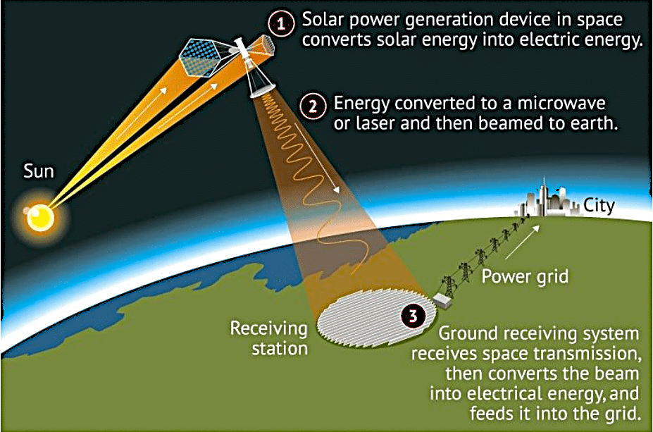
Microwave transmission is also safer than laser transmission, which poses risks to skin and eyes, is more susceptible to adverse weather and offers lower conversion efficiency. On Earth, a large rectifying antenna, known as a rectenna, receives the microwave beam and converts it into direct current (DC) electricity with about 90% efficiency.
Because rectennas occupy large areas, they are well-suited for installation offshore or in deserts. The orbiting photovoltaic (PV) arrays use high-efficiency gallium arsenide/indium phosphide (GaAs/InP) solar cells, converting 40-50% of incoming sunlight into electricity, compared with the 20-25% efficiency typically achieved by terrestrial solar panels.
A microwave generator converts the DC electricity into microwaves, which are transmitted to Earth through a phased-array antenna. The microwave signal is divided among thousands of miniature antenna elements, typically microchip patches arranged on a large flat panel. Each element incorporates a computer-controlled phase shifter that advances or delays the signal phase. By precisely controlling these phase shifts, the emitted waves combine constructively at the ground rectenna to form a single, concentrated beam.
In all other directions, the phase shifts cause the waves to cancel one another, reducing energy loss and enhancing safety. To maintain accurate beam alignment while both the satellite and Earth are in motion, SBSP uses a retrodirective system. The ground rectenna transmits a low-power pilot signal to the satellite, where the antenna array receives it. On-board electronics compare the signal phase, generate its conjugate and automatically steer the high-power microwave beam back along the same path. This process eliminates the need for continuous real-time tracking or beam-direction calculations.
Pros and cons
Beaming solar power from space is no longer science fiction and is becoming increasingly economically viable. Its key advantages and challenges include the following:
- Unlike terrestrial solar plants, orbiting PV arrays receive uninterrupted sunlight, unaffected by clouds or the day-night cycle. With an appropriate orbit, an SBSP system can generate clean electricity continuously throughout the year and supply power to terrestrial grids at a constant rate.
- SBSP can generate power at the gigawatt scale, comparable to nuclear power plants. Conventional ground-based solar farms require extensive land. For example, the Bhadla Solar Park in India generates 2.7GW from an area of about 160km². Although SBSP rectennas also require large sites, their land requirement is considerably lower than that of equivalent terrestrial PV installations. Typically, a ground-based solar plant requires about 4ha per megawatt (MW), whereas an SBSP rectenna requires about 1ha per MW. Raised a few metres above the ground on lightweight mesh structures, rectennas allow sunlight to pass through, enabling conventional or robotic farming beneath them. Ground stations can also be located offshore or in deserts to preserve fertile land.
- SBSP can generate approximately eight times more energy than an equivalent ground-based solar installation.
- Electricity can be transmitted wirelessly to almost any location on Earth without the need for transmission lines.
- SBSP has a low life-cycle emissions intensity of about 5gCO₂eq/kWh, making it one of the cleanest potential energy sources.
- Advances in reusable launch vehicles, improved solar-cell efficiency and lighter construction materials are steadily reducing costs. By 2050, the projected levelised cost of energy for SBSP is expected to fall to US$0.03-0.08/kWh, comparable with today’s global renewable energy cost of US$0.034-0.057/kWh.
- An operational SBSP satellite would be significantly larger than any structure previously deployed in space. Its size is determined less by power generation requirements than by the need to focus microwave energy into a beam narrow enough for efficient reception at the ground station.
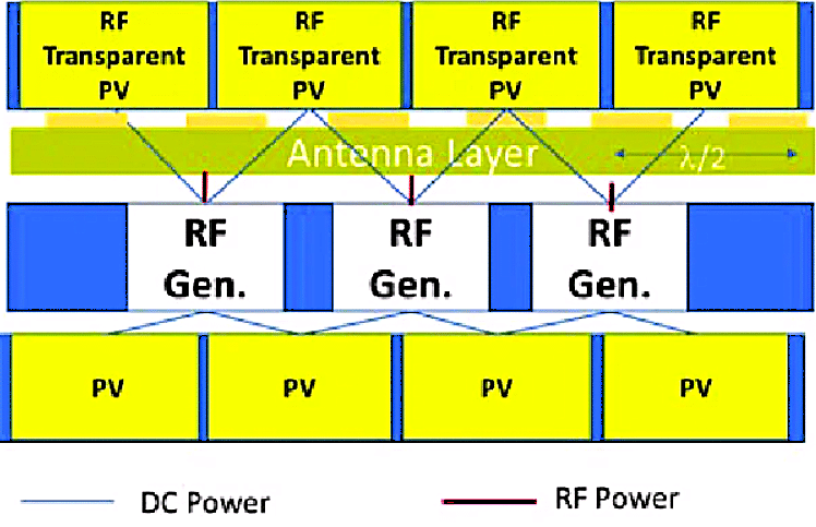
- Large orbiting PV structures are continuously exposed to micrometeorite impacts, increasing the risk of damage. This challenge can be mitigated through modular construction using polymer-based PV panels. Typically, modular PV sandwich tiles incorporate solar cells on both sides with a wireless power transfer layer between them (refer to Fig. 6). Micrometeorites generally pass straight through an individual module, allowing only the damaged module to be replaced rather than the entire array.
Challenges
Despite its promise, SBSP faces several significant technical challenges.
1. Propulsion technology: The most practical approach to deploying a full-scale SBSP system in geostationary orbit (GEO) involves a two-stage process. Individual subsystems are first launched into low Earth orbit (LEO), where they are assembled. The completed structure is then transferred to GEO using Hall-effect thrusters or the Variable Specific Impulse Magnetoplasma Rocket (VASIMR), a magnetoplasma propulsion system considered one of the most promising options (Fig. 2). VASIMR uses radio waves to ionise inert gases into plasma, which is then accelerated by magnetic fields to generate thrust. Although these electric propulsion systems show considerable potential, they still require validation for large-scale applications.
2. Wireless power transmission (WPT): Although WPT has been successfully demonstrated, transmission efficiency decreases over long distances because of beam misalignment and atmospheric effects. Transmitting microwaves from 36,000km above Earth requires a pointing accuracy of approximately 0.001°, making precise beam control a major engineering challenge.
3. Space environment: SBSP systems operating in GEO must withstand extreme temperatures, radiation and micrometeoroid impacts over an expected service life of about 25 years. Durable, ultra-lightweight materials can mitigate these effects, although they significantly increase system cost.
Fig. 2: Schematic of the Variable Specific Impulse Magnetoplasma Rocket (VASIMR) propulsion system proposed for transporting SBSP structures to geostationary orbit
4. Photovoltaic technology: Improving the power-to-weight ratio requires highly efficient multi-junction photovoltaic (PV) cells. Stacked gallium indium phosphide/gallium arsenide/germanium (GaInP/GaAs/Ge) cells (Fig. 3) can capture a broader solar spectrum, achieving efficiencies above 40%. Perovskite-silicon tandem cells, with efficiencies exceeding 30%, are another promising option because they are lightweight, flexible and potentially inexpensive. However, manufacturing such high-efficiency flexible cells remains technically challenging.
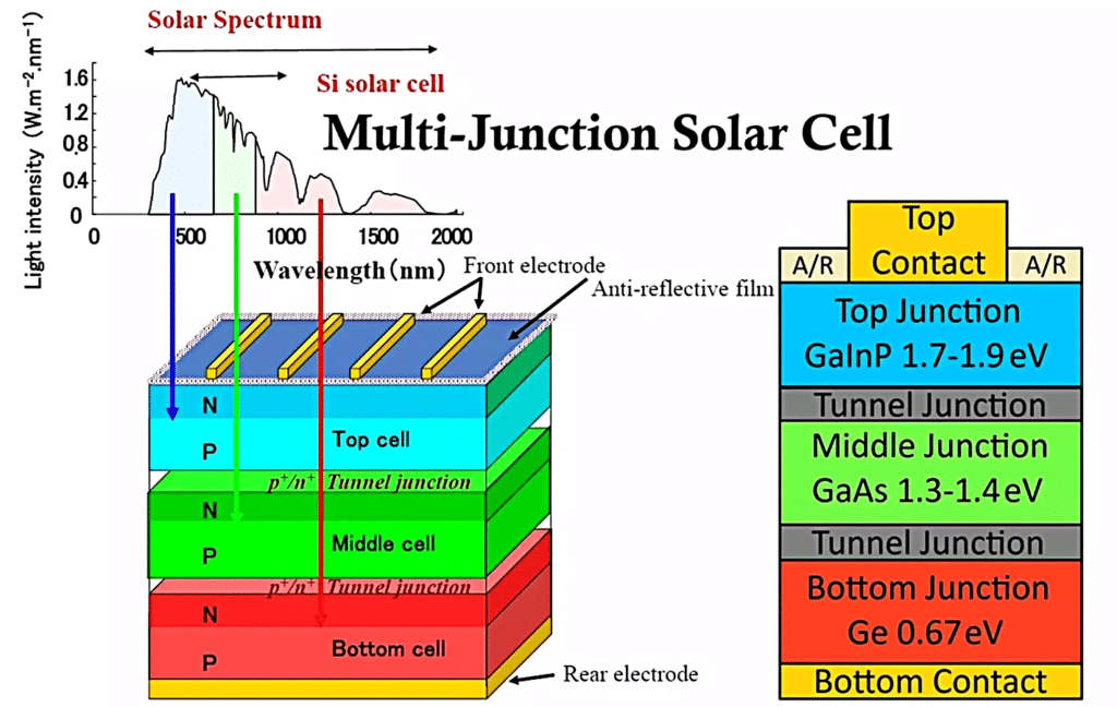
Fig. 3: Schematic of a high-efficiency multilayer solar cell (Source: www.intechopen.com Masafumi Yamaguchi)
SBSP system architecture
Although SBSP concepts have existed since the 1970s, the most practical approach is a modular swarmed architecture employing lightweight, high-efficiency thin-film PV arrays to minimise the mass-to-power ratio while transmitting energy through microwaves from GEO.
SBSP satellites operate approximately 36,000km above Earth in GEO, where their orbital period matches the Earth’s rotation. This orbit provides almost continuous sunlight and enables uninterrupted power generation. The modular design allows individual units to assemble autonomously into a single large structure. Microwave transmission is designed with a low power density, making it safe for aircraft and living organisms. Fig. 1 illustrates the schematic arrangement of an SBSP system operating in GEO.
Modular assembly
Because SBSP satellites can extend several kilometres in diameter, they are manufactured on Earth as modular tiles integrating PV cells, antenna electronics and structural trusses. Each module typically incorporates a flexible array sheet containing a self-synchronised network of integrated circuits and antennas that convert direct current (DC) electricity from the solar cells into radio frequency (RF) energy.
Standardised mechanical and electrical interfaces allow the modules to be assembled robotically in space.
Launch and transportation
The modules are designed to be highly compact, maximising launch payload efficiency. Reusable heavy-lift launch vehicles transport them to LEO, after which a space tug transfers them to GEO for final assembly.
In-orbit assembly (IOA)
Once in GEO, robotic systems assemble the modules into the complete structure, overcoming launch vehicle size limitations.
Assembly begins with the main structural truss and power bus, followed by Tri-Truss units with hexagonal hubs to provide rigidity. Solar array and antenna modules are then attached to the main truss and deployed from their compact stowed configuration.
After assembly, the system is activated remotely. The transmitting array calibrates its phase shifters to steer the microwave beam accurately, while power-generation tests verify the integrity of all modular connections.
Key modules PV panels
PV modules are designed to combine high efficiency with extremely low weight to minimise launch costs. Many proposed designs employ thin-film photovoltaics arranged in kilometre-scale arrays. These solar cells are manufactured by depositing photovoltaic materials in ultra-thin layers, typically less than 10μm thick, making them lightweight, flexible and well-suited to the high-temperature conditions encountered in space.
Typical thin-film cells comprise a transparent conducting tin oxide front layer, a cadmium telluride/copper indium gallium arsenide absorber layer, and a copper, gold or molybdenum (Mo) back contact. Emerging third-generation technologies, including perovskites and thermophotovoltaics, further improve performance. Thin-film cells typically achieve efficiencies of around 29%, while multi-junction concentrator cells incorporating thin-film technology have demonstrated efficiencies of up to 47% (Fig. 4).
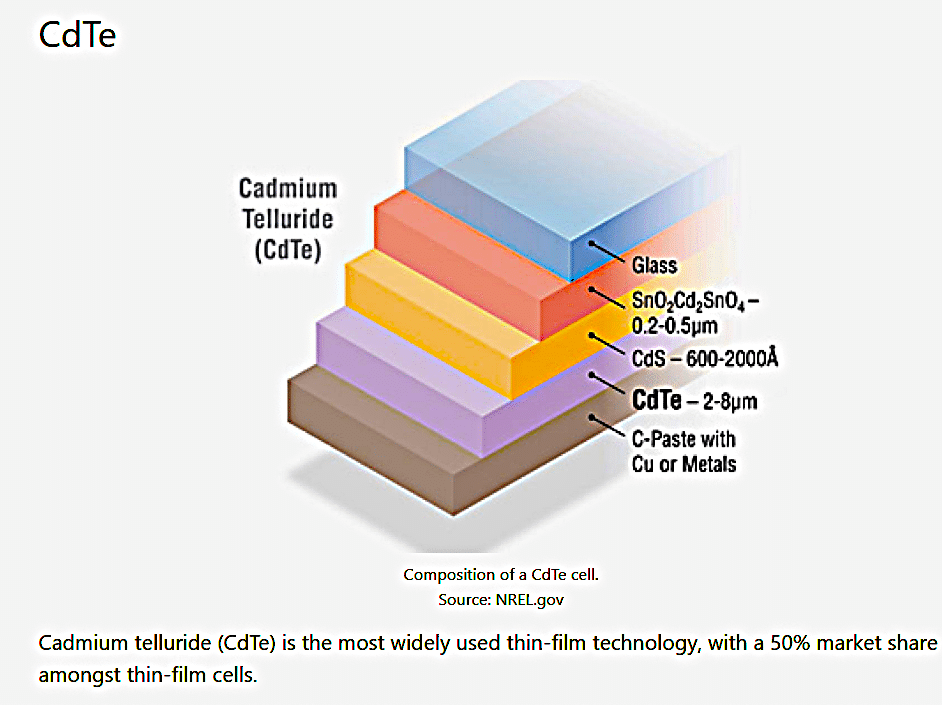
Fig. 4: Schematic of a thin-film photovoltaic (PV) cell
High-efficiency triple-junction and multi-junction gallium arsenide/gallium indium phosphide (GaAs/GaInP) cells achieve efficiencies of 28-29% in thin-film form, increasing to over 35% in optimised concentration systems. They also offer excellent resistance to radiation and high operating temperatures.
Epitaxial lift-off technology enables GaAs cells to be separated from their growth substrate and transferred to flexible sheets, significantly reducing weight. Nanostructures and back reflectors further improve light trapping and photon recycling, increasing voltage and efficiency, although at a higher cost (Fig. 3).
Advanced thin-film PV technologies can achieve power densities of approximately 17kW/kg.
Reflectors
The National Aeronautics and Space Administration (NASA) developed the Integrated Symmetrical Concentrator (ISC) for SBSP, using large thin-film mirrors to focus sunlight onto centrally located high-efficiency PV arrays, thereby reducing both PV area and overall cost.
The symmetrical design employs two reflector arrays that concentrate sunlight onto centrally positioned PV modules. Because concentration increases the operating temperature, the reflector geometry is optimised to keep the PV arrays within their safe temperature range.
The truss structure and concentrators rotate together to maximise solar collection while preventing overheating. In GEO, the system maintains a perpendicular-to-orbit-plane orientation for continuous, high-efficiency energy collection.
DC-to-microwave conversion
Electricity generated by the PV arrays is transmitted through conductive buses to onboard microwave transmitters, where it is converted into microwave energy.
Microwave power tubes, including magnetrons and klystrons, accelerate electrons that transfer their kinetic energy to electromagnetic waves, generating coherent microwave radiation.
A more advanced approach uses multilayer ‘sandwich’ modules that integrate PV cells, antenna layers and complementary metal-oxide-semiconductor (CMOS) electronics into a single thin tile (Fig. 6). PV materials are incorporated on both sides to maximise energy collection, while integrated power electronics convert DC electricity into microwave power for transmission to Earth.
These systems generally operate at 2.45GHz or 5.8GHz, the frequencies best suited to atmospheric transmission.
In NASA’s ‘Representative Design One’ (RD1) (Fig. 5), a phased-array antenna steers the microwave beam electronically towards a designated ground station without moving the entire structure. Precise beam steering is essential for maintaining high transmission efficiency.
On Earth, a rectifying antenna, or ‘rectenna’, typically several kilometres in diameter, receives the microwave beam and converts it into electricity using Schottky barrier diodes with an efficiency of approximately 90%.
RF-to-DC conversion at the ground station
The rectenna, first demonstrated by W. C. Brown in 1964, receives microwave energy and converts radio frequency (RF) power into direct current (DC) electricity at terahertz (THz) frequencies.
Operating at 2.45GHz or 5.8GHz, the rectenna converts the incoming microwave beam into DC electricity with an efficiency of about 90%. To handle the transmitted power, the receiving station comprises millions of rectenna elements.
Each element, typically a microstrip patch antenna or dipole array, receives the microwave beam even at high incident angles. The elements are commonly fabricated on lightweight substrates such as Kapton and are mounted about 1.2m (4ft) above a ground plane to maximise efficiency.
A Schottky barrier diode rectifies the induced alternating current (AC) into DC. Its low forward voltage drop and high switching speed make it well suited to efficient microwave-to-DC conversion.
An impedance-matching network maximises power transfer between the antenna and the diode. A low-pass filter suppresses higher-order harmonics generated during rectification, while a DC-pass filter smooths the output before it is inverted into alternating current and supplied to the electricity grid.
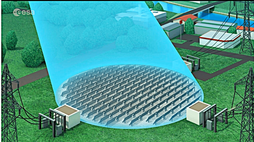
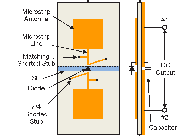
Fig. – 8 Scheme of Microstrip Element of Ground Based Rectenna (Source: www.semanticscholar.org IEEE International conference, 1 March 2017)
Typical operating regime
| Parameter | Value |
| Distance from Earth | 35,786km |
| Scaling factor | 0.77 |
| Solar panel area | 11.5km² |
| Solar constant | 1368W/m² |
| Incident solar energy | 15,689MW |
| Reflector illumination | 2-3 suns |
| Solar cell efficiency | 35% |
| DC-to-DC conversion efficiency | 90% |
| DC-to-RF conversion efficiency | 70% |
| Antenna emission efficiency | 90% |
| Atmospheric transmission efficiency | 98% |
| Beam collection efficiency | 95% |
| RF frequency | 2.45GHz |
Ground station
| Parameter | Value |
| Rectenna reception efficiency | 78% |
| Rectenna diameter | 6.0km |
| DC-to-DC conversion efficiency | 90% |
| Annual operating time | 99.7% |
| Power delivered | 2030MW |
Table. 1: SBSP in geostationary orbit (GEO)
Tracking and alignment
To maintain continuous power generation, the PV arrays and reflector mirrors must remain precisely aligned with the Sun using Sun sensors and active tracking systems that continuously rotate the collector arrays.
Because the solar arrays face the Sun while the transmitting antennas point towards Earth, and the angle between them changes throughout the year, the microwave beam is steered electronically using solid-state beam steering rather than by rotating the entire structure.
The ground rectenna transmits a low-power guidance signal that enables the satellite to lock onto the receiving station and maintain accurate beam alignment. Overall attitude control is provided by gyroscopes and momentum wheels, minimising the need for thruster corrections while maintaining precise pointing accuracy.
Cost economics
At present, SBSP in GEO is not cost-competitive with terrestrial renewable energy, which is approximately 50 times cheaper. The primary reason is the high cost of launching the large payloads required to GEO, approximately 36,000km above Earth. However, economic viability is expected to improve significantly as launch costs decline and large-scale manufacturing becomes feasible.
Launch costs currently account for the largest share of project expenditure, at approximately US$5600/kg. If these costs fall to around US$600/kg, PV efficiency increases to about 35%, advanced electric propulsion systems are adopted, and equipment is mass-produced, all of which are considered technically achievable, the projected levelised cost of energy (LCOE) could decline to US$0.03-0.08/kWh. At this level, SBSP would become competitive with terrestrial baseload electricity generation.
Reusable launch vehicles, such as SpaceX Starship, are expected to play a key role in reducing launch costs.
| Parameter | Value |
| Spacelift | US$32,595 million |
| Launch vehicle | SpaceX Starship |
| Launch-specific cost | US$5525/kg |
| Total capital expenditure (Capex) | US$49,017 million |
| Project finance hurdle rate | 13% |
| Manufacturer’s profit | 15% |
| Calculated LCOE | US$53/MWh (US$0.053/kWh) |
| Rated power delivered to grid | 2000MW |
| Orbit | GEO |
| Capacity factor | 100% |
| Annual energy generation | 17,467,400MWh |
| Total mass | 5900 metric tonnes |
| Design life | 30 years |
| PV efficiency | 35% |
| PV concentration factor | 2-3 |
| Microwave frequency | 2.45GHz |
| Satellite dimensions | 4500 × 3300m |
| Receiving rectenna radius | 3000m |
Table. 2: Estimated costs based on NASA RD1, January 2024
Further technological advances are expected to reduce costs even more. Increasing PV efficiency from 35% to 50%, together with lower launch costs, could reduce the LCOE to around US$0.04/kWh. Laboratory thermophotovoltaic cells have already demonstrated efficiencies of about 45%, indicating that these targets may be achievable. At such costs, SBSP would become competitive with conventional terrestrial power generation.
SBSP in GEO is widely regarded as a promising clean energy technology for 2050 because it offers near-continuous access to sunlight, avoiding many of the limitations of terrestrial solar power.
Current development plans envisage kilometre-scale lightweight PV stations assembled robotically in space between 2040 and 2050. Continued reductions in launch costs, together with PV efficiencies approaching 45%, are expected to lower the economic barriers to deployment.
The remaining challenges include reducing launch costs further, developing reliable robotic in-orbit assembly, mitigating space debris and ensuring safe, efficient wireless power transmission through the atmosphere. Nevertheless, ongoing advances in space technology continue to address these challenges.
By: Rathindra Nath Biswas. The author is a retired deputy general manager and former in-charge at MECON, Durgapur, West Bengal.