


Using an incorrect fuse in a circuit could have potentially disastrous consequences to people and equipment. In a solar system consisting of multiple strings of photovoltaic (PV) modules, strings are protected using direct current (DC) fuse links that are installed in a combiner or array junction boxes. This article attempts to give a sneak peak into the rationale behind the selection of fuses for a PV DC system.
AC versus DC
Alternating current (AC) is quite simple for a fuse to break as the AC source reverses the flow of electrons 100 times in a second in 50Hz circuits. When current reverses, it goes to zero in magnitude. A zero current flow is very easy for a fuse to interrupt; at this point, current flow stops and there is no longer any energy to sustain the arc across the melted fuse element.
DC, on the other hand, can be very difficult for a fuse to break. Here the current flows in a single direction. There is no zero point to aid the fuse in extinguishing the arc. DC fuses are relatively sophisticated devices that have a different construction as compared to simple AC fuses. DC fuses contain additional elements to extinguish the arc.
For AC and DC fuses, standard rated voltages are different and there is no strict mathematical relationship between these. A fuse rated at 1000V AC may be rated at 500V DC or 750V DC, dependant on its construction. As a general rule of thumb, a standard AC fuse will need to be derated by 50 per cent, that is, 1000V AC would be rated at 500V DC to be safe. However, you should consult the fuse manufacturer for test results or further specifications on each fuse before making any assumptions.
AC fuses are generally designed to take a load in excess of their rated current, sometimes 160 per cent to 200 per cent of their rated value for up to ten seconds. Within a PV system, current is limited by the constant-current-source design of PV modules, so obtaining enough current to break an AC rated fuse in a reasonable amount of time could be quite difficult.
DC rated fuses designed specifically for PV applications are meant to break at the rated current in a short time, providing maximum protection for cabling, junction boxes and PV modules. If the fuse does not state DC rating, or it is not mentioned on the product specification sheet, it could be that it is not approved for use in DC applications. Or it may be that the product has not been approved by an internationally-recognised electrical approval body or by the manufacturer, who may or may not have testing facilities to conduct the product test. Fuse holders should also be inspected for DC rating.
To protect yourself and your customers, always use the correct DC-rated product for your PV installations. If you use an incorrectly-rated product, you could be liable for any damage caused or for loss of life, in the event of things going wrong.
Using a fuse in a PV system
Fuses play a very important role in solar power projects. There are various locations where these are used in solar PV systems. The locations may include string combiner boxes, array boxes and even the DC side of the inverter system.
Fuses are also used on the AC side of the system. AC fuses are different as compared to DC fuses. But in this article we are considering only DC fuse design.
In case of a large number of strings connected in parallel, it is necessary to ensure protection of PV panels and the system against reverse current and over-current (OC).
Fuses are primarily used to protect the system against short-circuit and fire hazards. Fuses in PV installations are subjected to extreme conditions of the environment like exposure to sunlight that causes abnormal temperature of the fuse, which affects the performance of the fuse. Thus, sizing and selection of the right fuses and cables must be ensured.
Moreover, PV modules also produce continuous current. This makes it all the more important to have proper fuse sizing.
A fuse is an over-current device that is designed to sacrifice itself to protect electrical systems. Fuses are designed to open circuits when put under stress by excessive current flow caused by overloads or faults. Choosing the right fuse for an application will prevent fires and other damages that may be caused when something goes wrong. Typical problems may include a cable coming loose in the inverter circuit, a cable shorting to Earth, accidental cutting of a cable, an animal or rodent chewing through cabling, weather damage and so on.
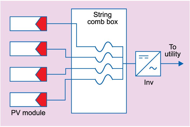
Fig. 1 illustrates a typical solar system from PV modules to inverter.
Fuse ratings
Fuses are rated by current and voltage, and are usually rated solely for AC, solely for DC or for both AC and DC. If incorrect fuses are used for DC applications, voltage rating may need to be derated and you would have to consult the fuse manufacturer for further information on their product. This is because of the greater arc energy that needs to be absorbed during the breaking process.
Key steps of fuse sizing for solar PV fuse selection
Following steps should be used for the proper sizing of a fuse of a string as per article 690.8 of National Electrical Code 2011.
1. Calculate maximum circuit current.
2. Calculate nominal fuse ampere rating.
3. De-rate fuse nonimal rating due to abnormal temperature conditions.
4. Calculate the nameplate ampere rating of fuse.
5. Verify fuse rating with respect to conductor rating.
Over-current protection (either fuses or breakers) must be included in a PV source or output circuit only if you have three or more array strings. PV module manufacturers usually specify the maximum number of strings that can be connected in parallel without adding any fuse protection, by means of maximum reverse current capacity of a PV module.
Fuses are usually placed inside a combiner box (if your system is using a combiner box) or inside the DC disconnector or an array junction box.
Most over-current devices are rated for a maximum operating temperature of 45°C. This works fine for everyday household wiring. On the other hand, because of their location outdoors or inside attics, PV components may be subjected to a lot more heat. Thus, if you plan to place any fuses or breakers in high heat, you should refer to the product specification sheets/temperature-raised-adjustment factors. Otherwise, the circuit may experience nuisance trips or blown fuses in hot weather.
To determine normal OC device rating, start with the following equation:
Circuit current rating=Imax
OC current capacity =Imax × number of module strings×1.56
On the DC side of the circuit, short-circuit current (Isc) is used for this calculation. If your fuse is to be placed inside a combiner or an array junction box, for example, Isc will be equal to the short-circuit current spec for the modules.
For our sample array of Sharp modules, the calculation is given as:
6.35A (short-circuit current)× 1.56 = 9.906A
Since fuses are sold in standard sizes (1, 2, 3, 4, 5, 6, 8, 10, 12, 15, 20, 25, 30 amps, etc), UL states that you must select the closest size at or just above the current rating value. For 9.906A, that means a 10A fuse.
For PV circuits incorporating a normal inverter with a transformer built into it, only one of the two polarities (positive or negative) in a pair, usually the ungrounded, or hot wire should have fuse. However, if you have a transformer-less inverter, both wires in the pair must have fuse.
In case you are wondering, the 1.56 multiplier in the current rating calculation is a shortcut that incorporates two NEC formulae that apply to PV circuits.
The first is: Imax×1.25, which equals what the NEC calls continuous current of a circuit.
The second formula is: Continuous current×1.25, which provides a cushion above the first value in order to avoid nuisance trips due to minor current fluctuations. Now, if you take 1.25×1.25 (or 1.25 squared), you get 1.56.
For our sample grid-tied system with a normal transformer-less inverter, a two-array string and a voltage (measured earlier) of 420.36V, the junction or combiner box we purchase must be rated for 1000V DC (that is, the standard size) to accommodate the positive and negative conductor for at least two strings and have a minimum 20A rating. So
Isc per string=6.35A
Number of strings in parallel=2
Total current flowing through the circuit=6.35×2=12.7A
Taking fuse rating factor of 1.56=12.7×1.56=19.81A
Fuse rating to be considered should thus be rated at >20A.
Therefore 20A conductor selected is 6sqmm copper cable that is capable of handling such current rating.
The system can now function safely.
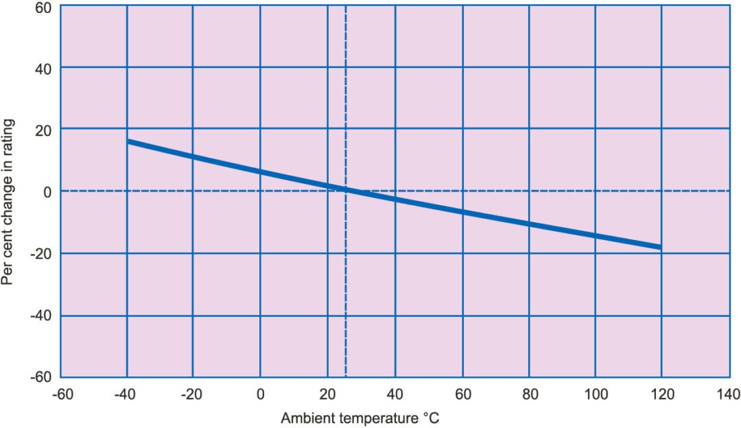
Fuse-deration curve with respect to temperature is given in Fig. 2.
IEC 60269-6 standard
Unlike typical grid-connected AC systems, the available short-circuit current within PV systems is limited and the over-current protective devices need to operate effectively on low levels of fault current. For this reason most manufacturers have conducted extensive R&D of fuse links that are specifically designed and tested to safely protect PV systems with high DC voltages and low-fault currents.
International Electro-technical Commission (IEC) recognises that protection of PV systems is different for standard electrical installations. This is reflected in IEC 60269-6 (gPV) standard, which defines specific characteristics that a fuse link should meet for protecting PV systems.
Manufacturers’ ranges of string and branch PV fuse links have been specifically designed to meet this standard. These PV fuse links are fully tested to the requirements of IEC 60269-6.
However, manufactures of PV fuse links exceed the requirements of IEC 60269-6 as these operate at 1.35 x In (1.35 times the nominal current). These also meet the requirements of UL 2579 and are thus suitable for protecting PV modules in reverse-current situations. While the standard does not recognise a specific symbol, a combination of symbols for fuse link and strings are often used to indicate that a fuse link is suitable for protecting strings in PV systems.