







Parking safely in a garage or other confined space can be challenging, particularly when rear visibility is limited. Even a slight miscalculation while reversing can damage the vehicle, nearby walls, pillars, or other parked vehicles. Although many modern cars come with factory-fitted parking sensors, retrofitting them to older vehicles can be expensive. This system can also be installed in auto-rickshaws and other vehicles, providing an audible warning and displaying STOP to alert the driver before a collision occurs. Fig. 1 shows the author’s prototype.
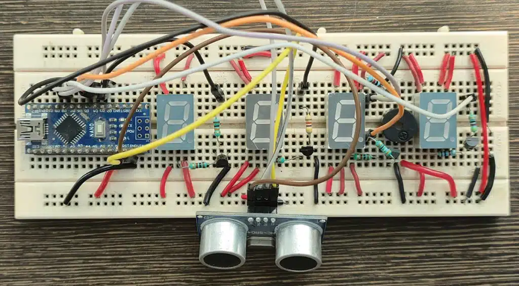
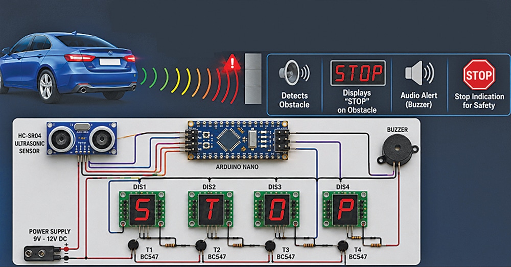
The system is based on an Arduino Nano and an HC-SR04 ultrasonic distance sensor. The sensor continuously measures the distance between the vehicle and the nearest obstacle by transmitting high-frequency sound waves and detecting their reflected echoes. The Arduino Nano processes the measured distance and compares it with a preset safety limit of 100cm. When an obstacle comes within this range, the controller activates a piezo buzzer through a BC547 transistor and displays STOP on a four-digit 7-segment LED display, providing both audible and visual warnings. The circuit operates off a regulated 12V DC supply, with BC547 transistors used to drive the display digits. Fig. 2 shows the complete system and its working principle.
Circuit and working
Fig. 3 shows the circuit diagram of the car/auto parking security system. It is built around an Arduino Nano (BOARD1), an HC-SR04 ultrasonic sensor (connected across CON2), four common-cathode 7-segment LED displays (DIS1-DIS4), five BC547 transistors (T1-T5), a buzzer (BZ1), and a few other components.
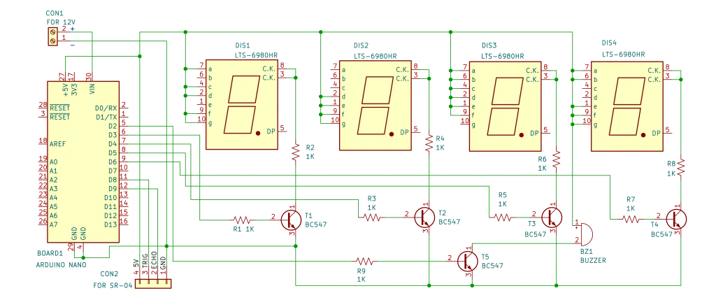
The circuit is powered by a regulated 12V DC supply connected to the Arduino Nano through CON1. The Arduino Nano provides the control logic, while the HC-SR04 ultrasonic sensor continuously measures the distance between the vehicle and the nearest obstacle. The output pins of the Arduino Nano are connected to the bases of five BC547 transistors. Four transistors drive the multiplexed 7-segment LED displays, while the fifth transistor drives the buzzer.
The HC-SR04 ultrasonic sensor has four terminals: VCC, GND, TRIG, and ECHO. During operation, the Arduino sends a 10µs pulse to the TRIG pin, causing the sensor to transmit an ultrasonic burst at 40kHz. When these sound waves strike an obstacle, they are reflected back to the sensor. The ECHO pin remains high for a duration proportional to the round-trip travel time of the ultrasonic pulse.
The Arduino compares the measured distance with a preset threshold value of 100cm. If an obstacle is detected within this range, the Arduino first activates transistors T1 through T4, which are connected to digital pins D3 through D6. These transistors enable the common cathodes of the four 7-segment LED displays, causing them to illuminate the word STOP and provide a visual warning to the driver. Simultaneously, the Arduino activates transistor T5, connected to digital pin D2, which drives the buzzer to generate an audible warning. When the obstacle moves beyond 100cm, the Arduino deactivates transistor T5, turning off the buzzer, and switches off transistors T1 through T4, thereby switching off all the displays. The threshold distance can be changed in the source code.
Software
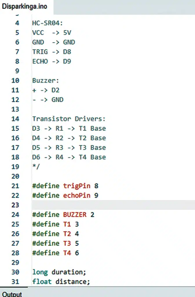
The program is written in the Arduino IDE and continuously monitors the distance between the vehicle and an obstacle using the HC-SR04 ultrasonic sensor. At the beginning of the program, symbolic names are assigned to the Arduino pins connected to the ultrasonic sensor, buzzer, and transistor drivers using the #define directive. Two variables, duration and distance, are declared to store the echo pulse width and the calculated distance, respectively.
The setup() function executes only once after power-up or reset. It initialises serial communication at 9600 baud for displaying the measured distance on the serial monitor. The TRIG pin of the HC-SR04 sensor is configured as an output, while the ECHO pin is configured as an input. Similarly, the buzzer and transistor driver pins are configured as outputs.
The main operation is performed inside the loop() function, which runs continuously. The Arduino first generates a 10µs trigger pulse on the TRIG pin, causing the HC-SR04 sensor to transmit an ultrasonic burst. The sensor then waits for the reflected echo from the nearest obstacle. Using the pulseIn() function, the Arduino measures the time for which the ECHO pin remains high. This pulse duration represents the round-trip travel time of the ultrasonic wave. The measured time is converted into distance in centimetres using the formula Distance=(duration ×0.0343)/2, where 0.0343cm/µs is the speed of sound in air and the division by two accounts for the forward and return journey of the sound wave. Fig. 4 shows a snippet of the source code.
Finally, the calculated distance is transmitted to the serial monitor for testing and debugging purposes. A delay of 500ms is introduced before repeating the measurement cycle. The measurement cycle then repeats continuously.
Uploading the source code to Arduino Nano
Install the Arduino IDE and connect the Arduino Nano to the computer using a Mini-USB cable. If the Arduino IDE is already installed, skip the installation step. Launch the Arduino IDE and open the provided .ino source file. From the Tools menu, select Board→Arduino Nano, Processor→ATmega328P (or ATmega328P (Old Bootloader) for most clone boards), and choose the correct COM port corresponding to the connected board.
Click the Verify (✓) button to compile the program and ensure that it is free of errors. Once the compilation is successful, click the Upload (→) button to transfer the code to the Arduino Nano. During the upload process, the built-in RX and TX LEDs will blink. When the message ‘Done Uploading’ appears, the program has been successfully uploaded, and the Arduino Nano is ready for operation.
| Parts List |
| Semiconductors: Board1 – Arduino Nano (ATmega328P) DIS1-DIS4 – LT5-6980HR/LTS543, common-cathode 7-segment display T1-T5 – BC547 NPN transistors Resistors (all 1/4-watt, ±5% carbon): R1-R8 – 1kΩ Miscellaneous: CON1 – 2-pin screw terminal connector CON2 – 4-pin connector, for HC-SR04 BZ1 – 5V buzzer – HC-SR04 ultrasonic sensor – Designed PCB – Enclosure, solder – Connecting wires – 12V battery/adaptor |
Construction and testing
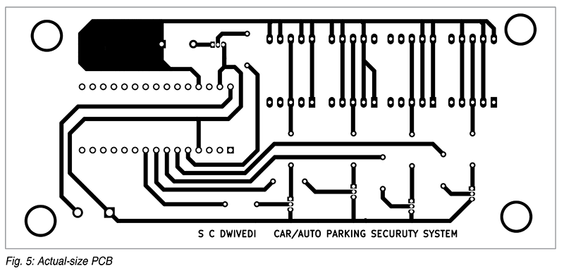
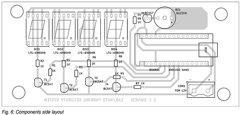
An actual-size, single-sided PCB layout for the car/auto parking security system is shown in Fig. 5, and its component layout is shown in Fig. 6. After assembling the circuit on the PCB, mount it inside a suitable enclosure to protect the circuit. Alternatively, the circuit can be assembled on a general-purpose PCB or a breadboard, ensuring the correct orientation of the Arduino Nano, BC547 transistors, resistors, connectors, and 7-segment displays.
After completing the assembly, carefully inspect all solder joints for shorts or dry connections. Connect the HC-SR04 ultrasonic sensor to the PCB using suitable jumper wires, and power the circuit with a regulated 12V DC adaptor. Upload the program to the Arduino Nano using the Arduino IDE, and open the serial monitor with the baud rate set to 9600bps.
For testing, place an object in front of the ultrasonic sensor and observe the measured distance displayed on the serial monitor. As the object comes within the preset threshold distance of 100cm, the buzzer should sound, and all four 7-segment displays should illuminate simultaneously. When the object moves beyond the threshold distance, both the buzzer and the displays should switch off. The threshold distance can be modified in the source code, and the updated program can then be uploaded to the Arduino Nano.
Installation
Mount the ultrasonic sensor on the rear of the car, near the number plate, facing directly towards the approaching obstacle or vehicle. For suitable alignment, mount the sensor approximately 60cm to 80cm above the ground, at about the height of the vehicle’s rear bumper.
Position the display and buzzer unit where it is clearly visible to the driver while reversing and where the warning sound can be heard easily. Connect the system to a regulated 12V DC power supply and test its operation by slowly reversing the vehicle towards the sensor. As the vehicle approaches the preset stopping distance, the buzzer sounds and the display illuminates STOP.
The system can also be used in home garages, apartment parking areas, warehouses, workshops, and loading docks where accurate and safe vehicle positioning is required.
S.C. Dwivedi is an electronics enthusiast and circuit designer at EFY