





Texas Instruments has released a 16-cell battery pack reference design with low standby power, accurate cell-voltage monitoring and protection features for high-capacity battery applications.
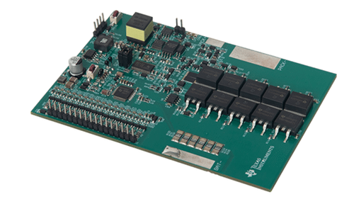
Texas Instruments has released a reference design for a 16-series (16s) lithium-ion (Li-ion) and lithium iron phosphate (LiFePO4) battery pack. The design monitors individual cell voltages, pack current, cell temperature and metal-oxide-semiconductor field-effect transistor (MOSFET) temperature. It also provides protection against cell overvoltage, undervoltage, overtemperature, charge and discharge overcurrent, and discharge short circuits.
The reference design uses five pairs of low-side N-channel MOSFETs for charge and discharge control. According to Texas Instruments, this architecture provides strong switching capability for handling higher charge and discharge currents. An auxiliary power-supply strategy reduces power consumption to a typical 100 µA in standby mode and 10 µA in ship mode.
The design provides cell-voltage measurement accuracy of ±5 mV at 25°C, ±10 mV from 0°C to 60°C and ±15 mV from –40°C to 85°C, without calibration. Additional protection features include cell open-wire detection, thermal host watchdog, Controller Area Network (CAN) bus fault protection and charge and discharge MOSFET short-circuit protection.
The reference design is intended for high-capacity battery applications such as telecom and server battery backup units (BBUs), residential energy storage systems (ESS), electric motorcycles and portable power stations. Texas Instruments has also categorised the design under industrial battery-pack applications and data-centre systems.
Texas Instruments provides supporting resources for the reference design, including a design guide with verified performance data, bill of materials (BOM), assembly drawing, computer-aided design and engineering (CAD/CAE) files, Gerber files, printed circuit board (PCB) layout and schematic. The fully assembled board is intended for testing and performance validation and is not available for sale.
To read more about this reference design, click here.