Position sensors are considered to be a large family with many different types of sensors, however each sensor in this family is unique with respect to the principle on which it works and its construction. So is the case with potentiometric position sensors, which are considered to be the most inexpensive of all position sensors.
One important thing that I would like to clarify first is that, we are not talking about ‘potentiometric sensors’. Potentiometric sensors are used to measure the electrical potential of an electrode while no current is flowing through it. They are a type of chemical sensor.
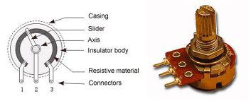
On the other hand, the star of this story is the potentiometric position sensor, which is used to measure the rotary or linear displacement or position of an object using the technology developed for potential military applications which then were adapted to industrial segments. They are also referred to as “Potentiometers”. Some of these require physical contact with the moving targets whereas there are other types of potentiometers that are non-contact types, use the Hall effect IC technology and have long life as compared to the latter ones. One can refer a potentiometer as a normal circuit where the resistance can be changed manually with the help of sliding contacts.
Classification
It becomes very important to understand the classification of the product we are going to purchase, as this would help us narrow down our search. There are many different ways to classify Potentiometers. The broader categorization is based on their function or the area of application:
- Angle Sensor: These are usually round, rotary sensor used to measure the angular displacement of the body it is in contact with. They are also referred to as rotary potentiometers.
- Linear Sensor: These are found in different shapes and sizes which does not affect the linear displacement of the body it measures.

Another way to classify them is based on the materials they are made of:
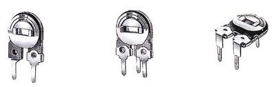
Wire wound potentiometers: These types of potentiometers are made by winding several rounds of wire around the shaft of a material that is non-conducting. An adhesive is used to bond the turns of the coil together. Now when body to which this is in contact with moves, the slider moves on the track of the potentiometer and makes contact with successive turns of the coil. It is considered that larger the number of turns of the coil, better is the coil resolution. Mathematically resolution is inversely proportional to the number of turns, so lower the value of resolution, the better it is. The wire wound potentiometers have low noise and are considered to be rough and tough mechanically.

- Carbon film potentiometers: They are made by depositing carbon composed ink on an insulating body. The insulating body in most of the cases is phenolicresin, which is one of the most commonly used materials for potentiometers. These are cheap and are better in resolution than the wire wound potentiometers. They have reasonable life and tolerable noise levels.
- Plastic film potentiometers: These potentiometers are made of specially saturated plastic material with resistance characteristics that can be controlled properly. These are used for both rotary as well as translational slider movements. They have better resolution than the wire wound potentiometers, can be used for a longer period of time without much wear and tear and produce low noise.
Then we can also classify them based on their design structure.
- Linear taper potentiometer: In this the device has a resistive element of constant cross-section. It does not describe the geometrical characteristics of the resistive element however it explains the electrical characteristics of the device. In this type of sensor the resistance between the wiper and any one end of the terminal is proportional to the distance between them.
- Logarithmic potentiometer: The resistive element that it has is either tapered in from one end to the other or the potentiometer is made of a material with varying resistivity from one end to the other. It is called as a logarithmic potentiometer because in this the output voltage is a logarithmic function of the slider position. They can also be simulated with a linear potentiometer using an external resistor, however this simulation would not result in a very accurate device. These type of sensors are more expensive.
Finally, they can be classified on their working style-contact and non-contact. All the types of potentiometers discussed above can be classified under these categories:
- Contact type: These potentiometers consist a moveable contact on an electrically resistive component. All the earlier versions of this sensor were made from a resistive wire (like Nichrome) that was wound around an insulating former. The moveable contact that acts as a wiper, makes some contact with the wire that is wound and slides along it. The wiper acts as a variable resistor also known as Rheostat. Thus this sensor works on the principle of changing resistance of the wire with respect to its length. The resistance of the wire is considered to be directly proportional to its length, so if the length increases, resistance does too. In order to measure the angular displacement, only two terminals of a potentiometer are used. It works on the principle that resistance changes with change in angle. The variable value of resistance helps us to find the actual angular displacement.
“Due to its working principle it is also sometimes referred to as Resistive Potentiometer. It is a very special resistor with three terminals”.
- Non Contact type: These potentiometers have a pair of planar magnets that are disposed opposite yet parallely to each other on a magnetic yoke. The polarity of these magnets are arranges in such a way that they form parallel magnetic fields around magnetic detection element. This detection element is retained on a support shaft that connects to a rotary shaft on an actuator and can rotate freely relative to the stationary one. As soon as this rotary shaft is rotated, there is a change in the output of the magnetic detection element which allows the detection of the rotation angle of the shaft. The non-contact types of potentiometers are considered over the contact type due to their long life and reliability. These sensors are extremely small in number due to which Hall effect position sensors are used as their replacement.
How to Select?
Now let us suppose a situation where we enter a shop to buy a potentiometric position sensor and find ourselves in a dilemma of how to select one, as the shop has so many options and we do not want to buy something that would not be accurate as per our requirement. This is a real difficult situation because the shopkeepers cannot help us unless we tell them our requirements. In such situations a good understanding of the different parameters of the device helps a lot. In order to select a potentiometric position sensor following parameters should be considered are as follows.
Linear or Rotary?
This defines the motion of the sensor in order to identify it’s track of movement. It helps to identify if the sensor would be useful in calculating the angular displacement or the linear displacement.
Dimensions and Weight
This parameter is very helpful to identify the application this sensor can be used for. If a sensor is of larger size and is very heavy, it cannot be used in smaller applications. Dimension is usually measured in millimeter (mm) whereas weight in grams (g).Life
These sensors are all contact type sensors where mechanical wear and tear hamper deteriorates their working capability and thus their life. The life of a pod is expressed in number of movements.
Measurement Range
It provides the range of operation of the sensor within which it can provides an accurate value. It may be calculated either in degrees or in mm depending upon the type of potentiometric position sensor being used.Repeatability
It is the variations in measurements by a single person or sensor on the same device under same conditions.
Independent Linearity
It is the maximum deviation of the actual function from the straight line that acts as a reference with the slope and the position that has been chosen in order to minimize any deviations. It is expressed as a percent of the total applied voltage.
Operating Temperature
It defines the range of temperature within which this sensor can operate without being affected by the environment. It is expressed usually in degree Celsius.
Vibration
It is the frequency of oscillation of the sensor about an equilibrium position. It is expressed in hertz (Hz).
Shock/ Noise
It is a disturbance in the function of the sensor due to an unexpected impact. It is a form of vibration that may be described in terms of acceleration, force, velocity or displacement.
Output
A potentiometer may give either a digital or an analog output which makes it an important parameter that should be considered for the application we would use it for.
Click here to view Table to help select Potentiometric Position Sensor
Pros & Cons
Every product in this world has some positive as well as negative features and so do the Potentiometric position sensors. The disadvantages, although few in number, are with respect to the contact type sensors.
- Inertial loading: These types of sensors are affected highly by the environment, at times. Dust gets easily accumulated between the resistive surface and the slider thus increasing the resistance than the actual value. This results in incorrect output voltage or in some cases loss of total voltage.
- Limited Bandwidth: Precautions need to be taken so that the working of these types of sensors is very smooth and slow, so that they can measure the accurate and continuous voltage. Now if the slider is moved very fast, chances are there that the contact would bounce, which would result in an intermittent output voltage.
- Wear and Tear: At times the frictional forces between the slider and the resistive surface increases so much so that the actual movement of the body is also limited. Again the more the frictional forces, the more is the wear and tear of the sensor. This also limits the number of operating cycles.
The negative points are just not enough because if we want to select a sensor for the different applications, we should also be able to identify it’s advantages for the right selection.
- Ease of implementation: Due to their mechanism, they are easy to use and do not require any additional implementation assistance
- Low price: They have quite low price so are widely used.
- Analog output: They provide high amplitude, analog output thus no signal processing is required and the output can be accessed easily.
- Proven technology
- Ease to add additional channels to increase reliability
- Easy Availability
Sneha Ambastha is a technical journalist at EFY Gurgaon