


[defineweblang title=”Change Video Language” language=”English,Hindi”]
[getvideolang url= “https://www.youtube.com/embed/XZpZxjV2Smo” language=”English”][/getvideolang]

[getvideolang url= “https://www.youtube.com/embed/C2XWFasJlb0″ language=”Hindi”][/getvideolang]
[/defineweblang]
In this project, we will be using ESP8266 12E manufactured by Lolin to make a Chatbot  that can control our home applications. To chat with our chatbot, we will use Facebook messenger platform. Also, we will integrate some AI into our chatbot using Chatfuel. It will then be integrated with IFTTT and Adafruit IO. Adafruit IO is linked to our ESP8266 at the hardware side. In a gist, the output pins of ESP8266 will be controlled through our Facebook Messenger Chatbot.

The project is amazing for those who want to integrate some AI into their IoT.
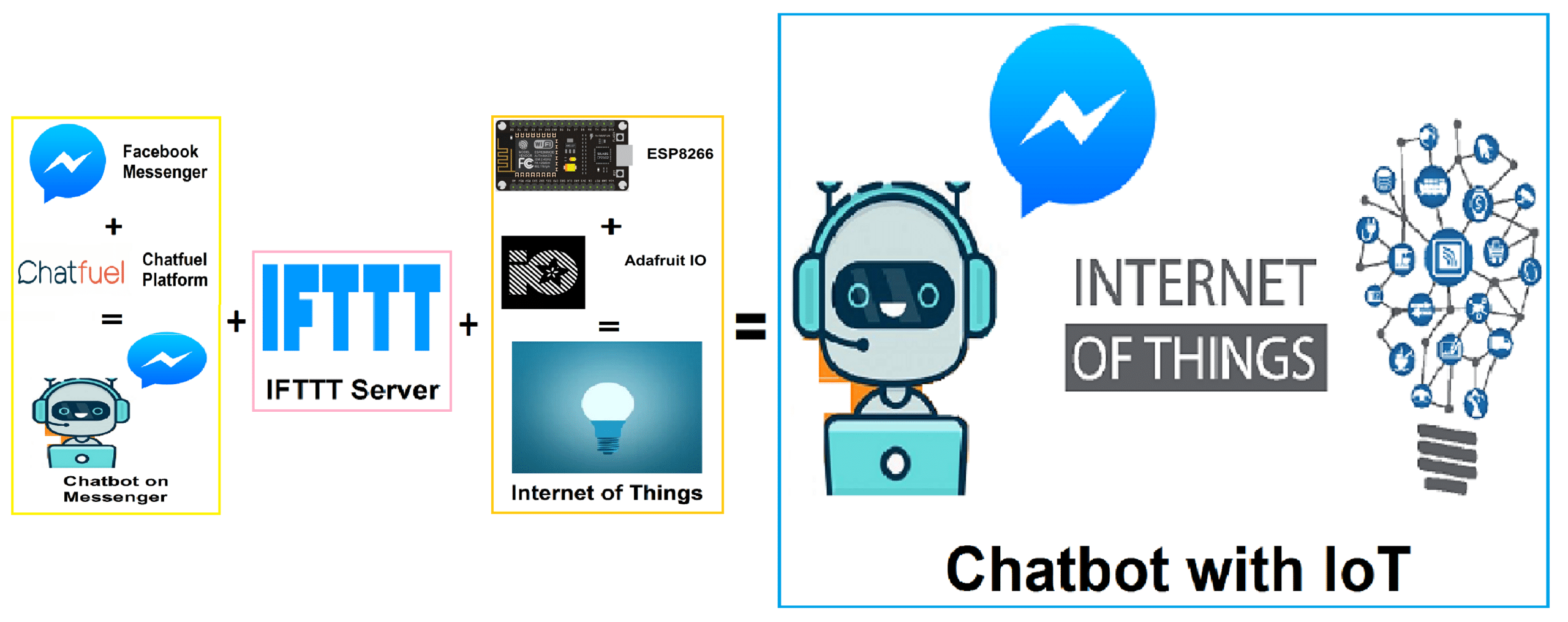
The Fig. 1 will give you some idea of the process we are up to in this project. The IoT and the Chatbot segments are developed separately. Then, we will merge these two to make our final Chatbot.
Material to get started:
- ESP8266 12e NodeMCU manufactured by Lolin (Check the datasheet, if you are using a different version.)
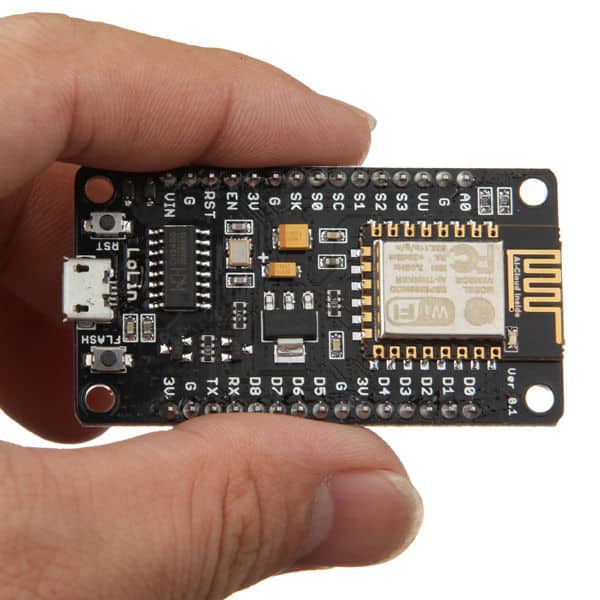
Fig. 2: ESP8266 12E by Lolin - USB Type C cable to program ESP8266 12e from a laptop or PC. Most Android phones use this type of cable.

Fig. 3: USB Type C Cable - Relay Module – Relay is an electro-mechanical switching device. In a relay, we can control switching AC or DC appliances digitally by providing input to relay input pins. Here we have used a 1-channel relay operating on 5 Volts.
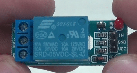
Fig. 4: 1 Channel Relay Module To connect your AC appliance, use the following connection with the Relay Module use the following connection. The Signal pin is IN.
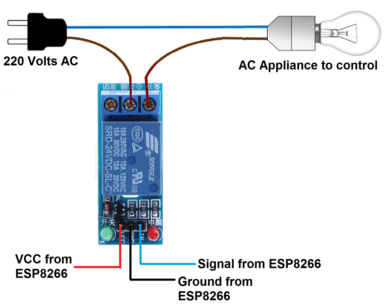
Fig. 5: Relay Connection With some wires and breadboard.
Back End Set-up:
-
Set-up with Facebook Messenger:
We need a Virtual human to chat with. For this, we will create a Facebook Page.

To create a Facebook Page, click here and Get Started with Community or Public Figure. Fill your Page name and Category.
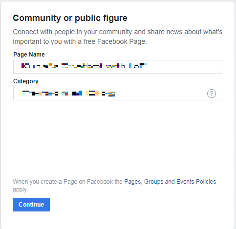
If you wish, you can even add a Profile Picture and Cover Page to it. You must also hide your Page name and do settings so that your page is not available publicly.
2. Set-up with Chatfuel Platform:
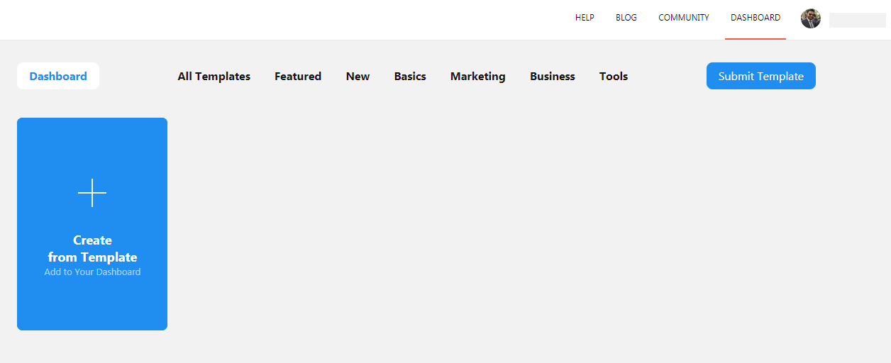
Go to Chatfuel Platform from here. Sign Up with the same Facebook profile you created the Page and go to the Dashboard and select “Create from Template” and then “Blank Bot”.
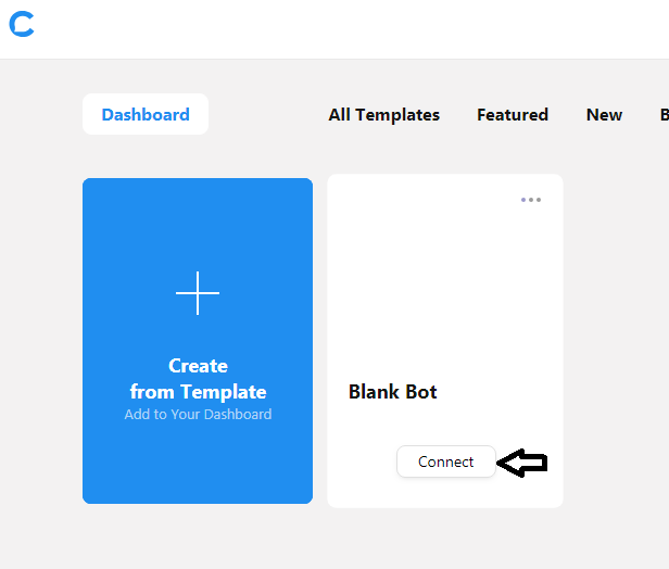
Now the Blank bot is created in the Dashboard and you need to connect it with the Facebook Page. So, click “Connect”.
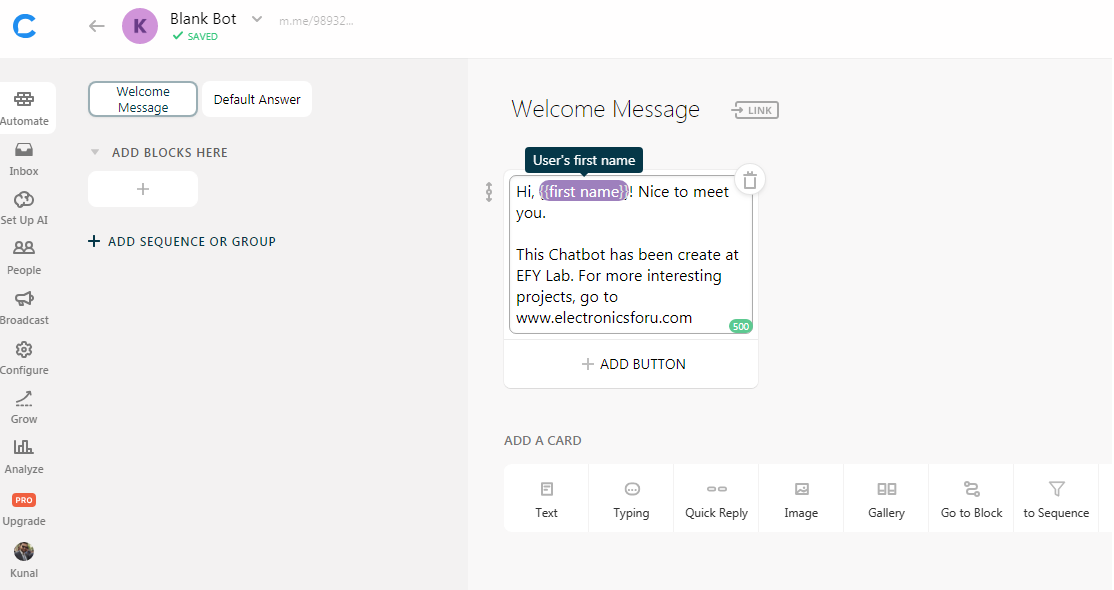
Now Select the Facebook Page you want to connect with. Now you can start with the AI part of the Chatbot.
Go to Automate and edit the Welcome Message by changing the User’s First name.
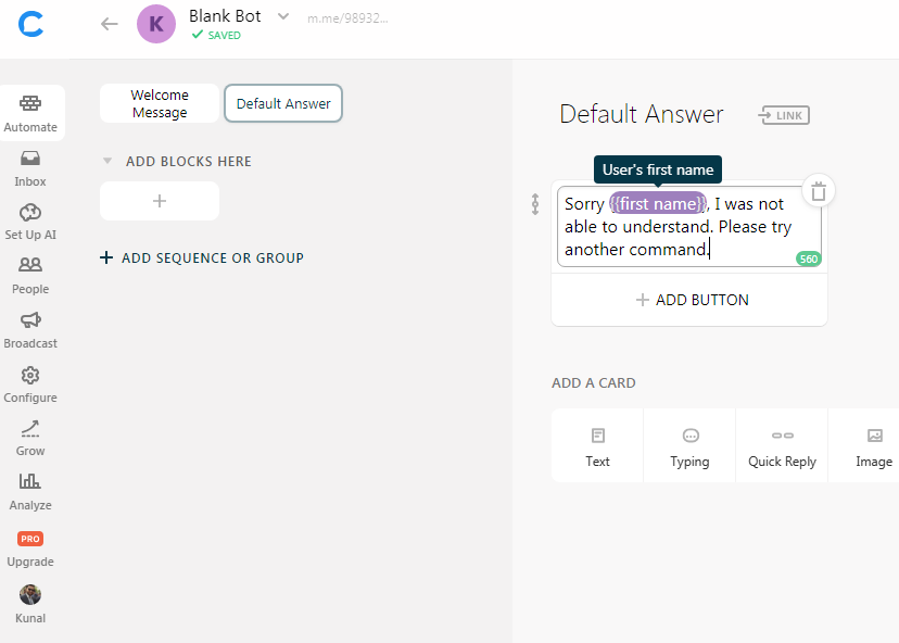
Now Click the Default Answer and edit it in the same way. The default answer is replied for the commands not programmed in your Chatbot or for any unexpected error.
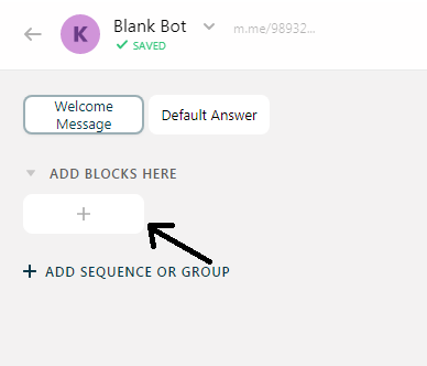
Now, we start adding Blocks. Blocks are the functions that will be executed on chat commands. Click on the + symbol to add these blocks. These functional blocks will hit the APIs of IFTTT server.
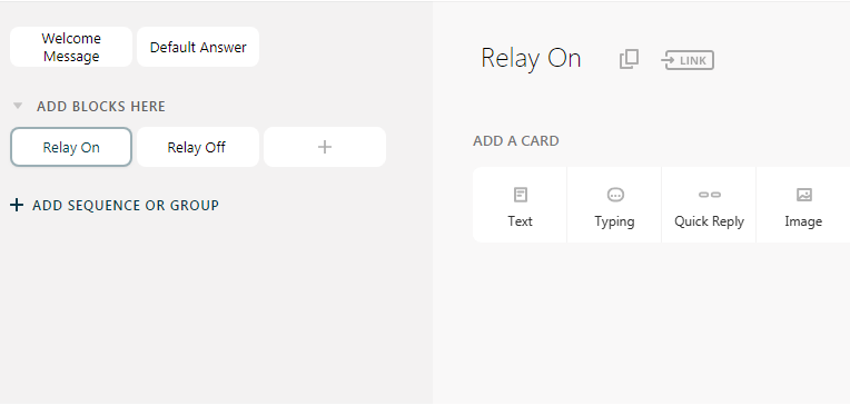
Create two blocks and rename them as Relay On and Relay Off.
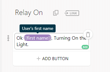
Select Relay On block and add a Text card to it. This text card is a reply that our Chatbot gives on performing this certain block.
You can edit this Text Card in your preferred answer. Do the similar settings for the Relay Off with Light Off message.
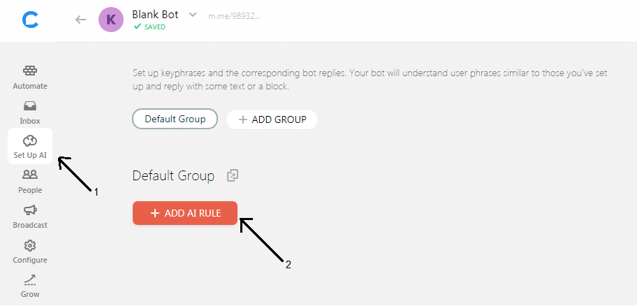
Now, click on Set Up AI (1) and select + ADD AI RULE (2) and fill the AI. This is the main set up of its AI.
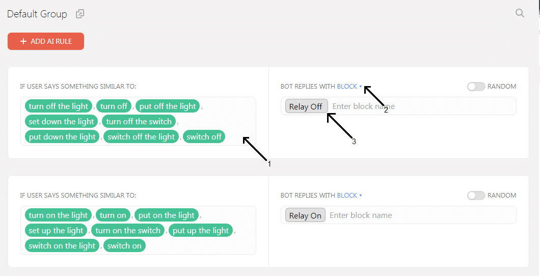
Add its AI rules by written all permissible phrases a user can say (1) and reply with Blocks (2) and add the corresponding block (3). To add each phrase simply type the phrase and Enter.
We will leave it here. Further settings will be done after setup with IFTTT.
3. Set-up with Adafruit IO:
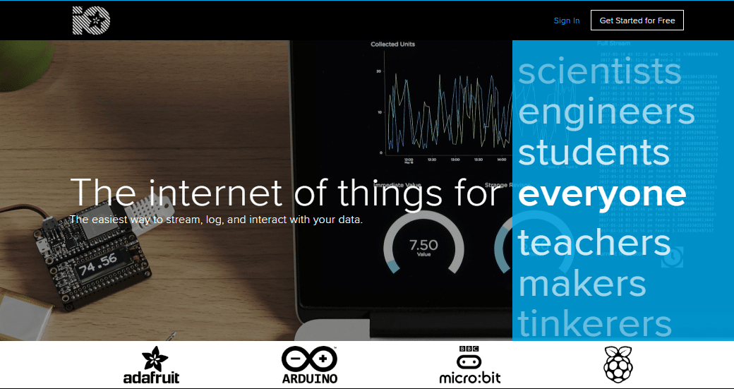
Adafruit IO serve is the IoT end. Here our ESP8266 gets connected with its server and executes our desired command. Go to Adafruit IO. Sign Up or Sign In to your Adafruit IO account.
After creating Adafruit, you should be taken to Adafruit Home Screen.
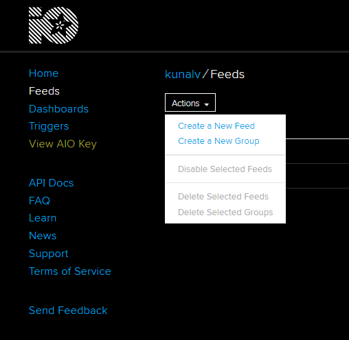
Now Select Feeds from hand menu and Click Action > Create a New Feed from the drop-down menu.
Give this any name you wish, I created “onoff”. Now, Go to Dashboards > Actions > Create a New Dashboard. Similarly name this one also, I named it “LightAutomation”.
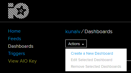
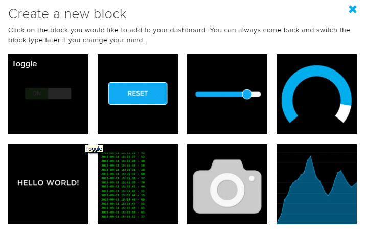
And click on + “Blue +” on the Top right side of your Dashboard to create a new block.
Select “Toggle” Block.
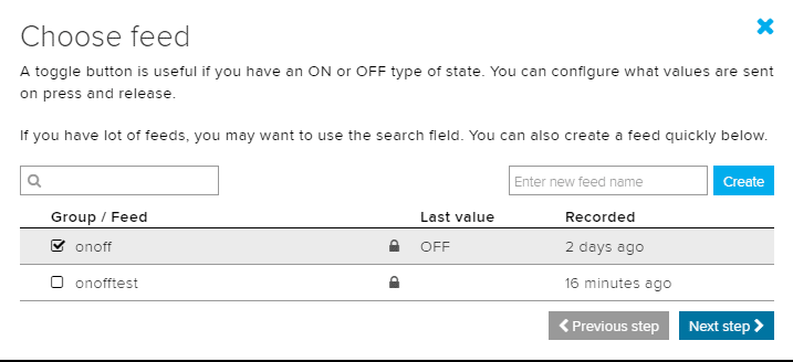
Now, choose your feed and click “Next Step”.
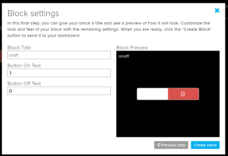
Fill the block settings and “Create the Block”.
Now let’s merge everything with IFTTT.
- Set up with IFTTT:
Create an account on IFTTT (https://ifttt.com) by Signing Up with your same Google Account you are using in your phone.
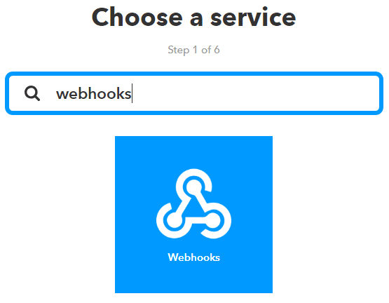
Now go to My Applets > New Applet > Click “ + this “. Search for the service Webhooks and select it.
Select Request a Web Service and Fill the event name and Create Trigger.

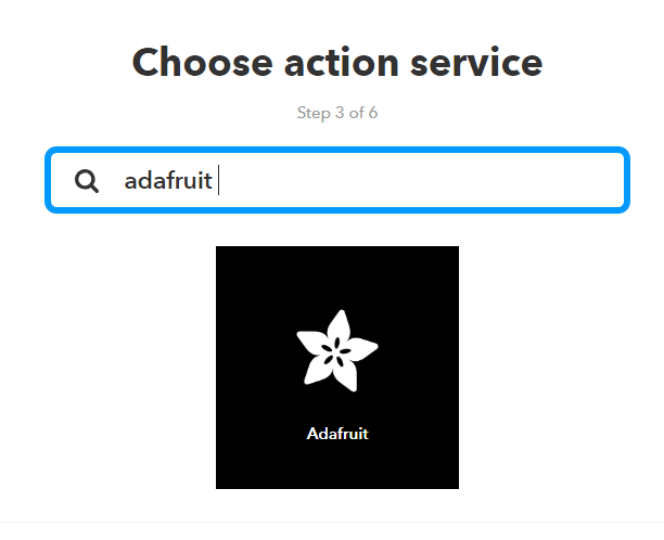
After creating Trigger, we must fill the Action Service. For that click on + that.

Now, search for the Action Service Adafruit and select it.
For the very first time, this will ask your Adafruit Login Credentials. Fill your Adafruit IO account details there.
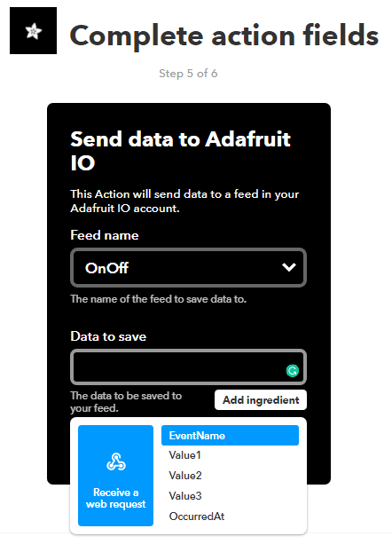
Choose “Send data to Adafruit IO” action and fill the Action field by choosing your “Feed name” and “Data to Save” as Value 1 in Add Ingredient. “Create Action” and click “Finish”.
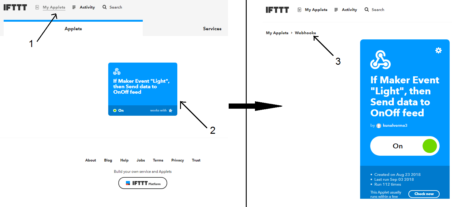
Now go to My Applets (1), select your Applet (2) you created and Click on Webhooks (3).
Now, we need the API URL. We can get it from Webhooks Settings. So, click on Settings. Copy this URL and save it somewhere we will need it later.
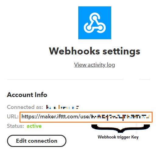
We will make 2 links for light on and light off from this single URL.
For Light On: https://maker.ifttt.com/trigger/<your event name>/with/key/<your webhook trigger key>/?value1=1
For Light Off: https://maker.ifttt.com/trigger/<your event name>/with/key/<your webhook trigger key>/?value1=0
Copy these two links and save them. We need them for Chatfuel Integration.
You can test these two links by hitting them directly in your web browser and checking your Toggle Switch created at the Adafruit IO server.
Let us now integrate everything up.
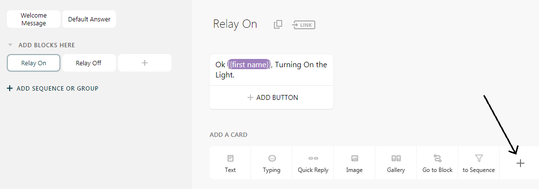
Do you remember the Relay On and Relay Off Blocks we created in Chatfuel platform? Let’s get back to them.
We now will add JSON APIs to them. Select the + in Add a Card menu of Relay On block.
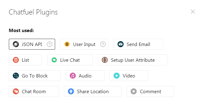
Click on JSON API from Chatfuel Plugins Menu.
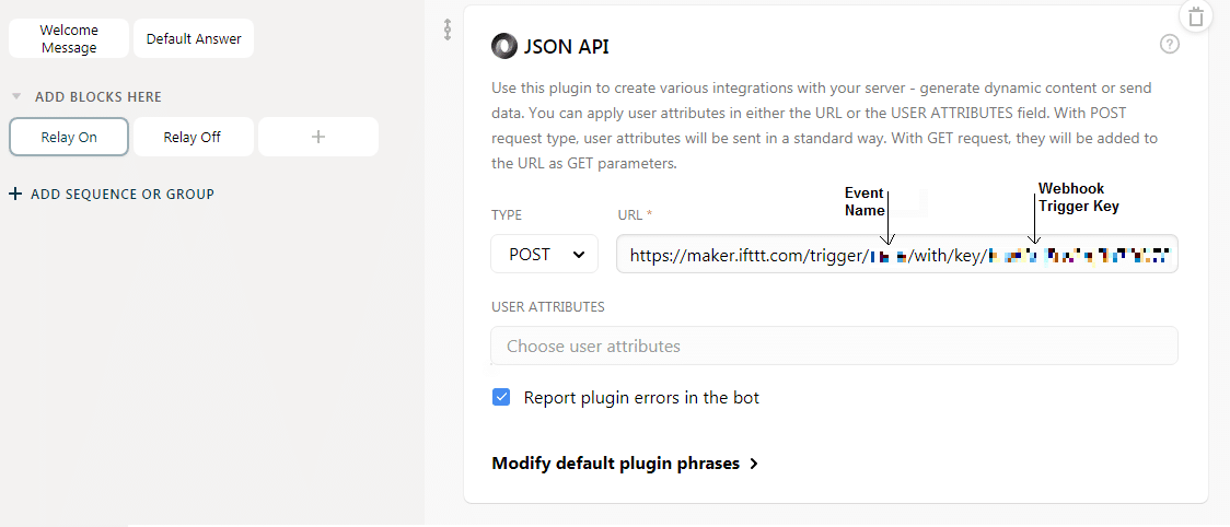
Now, select the type as Post and enter the link we made for Light On. Paste this link in the URL Tab here.
Similarly, we will do this for Relay Off.
Now, our Chatbot is ready and is connected to our IoT Server (Adafruit Server).
You can test with Chatbot with Inbox section of Chatfuel. Your Adafruit IO server will get updated in real time.
Steps for the Software Setup:
(Ignore this step if you already have the setup for Arduino IDE)
To code the ESP8266 we need an Integrated Development Environment, and we will use the Arduino IDE software. Arduino IDE is a cross-platform application. It is written in Java and coded in C/C++ with some special rules. To download the latest Arduino IDE from here.
Arduino IDE does not contain support of ESP8266 family so to install the ESP8266 Boards library in Arduino IDE, follow the instructions below.
- Open Arduino IDE. Go to File > Preferences.
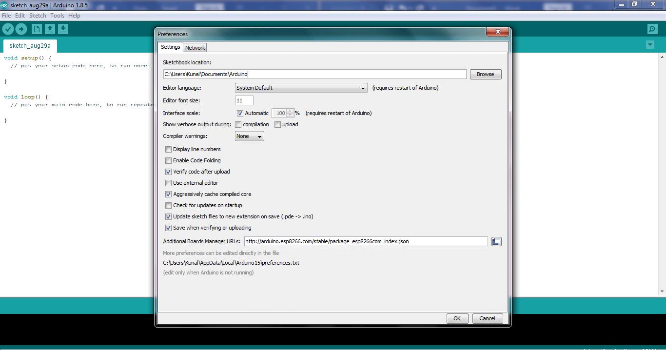
Fig. 34: Preferences in Arduino IDE - Enter http://arduino.esp8266.com/stable/package_esp8266com_index.json into the “Additional Board Manager URLs” field. Now, click the “OK” button.
- Go to Tools > Board > Boards Manager.
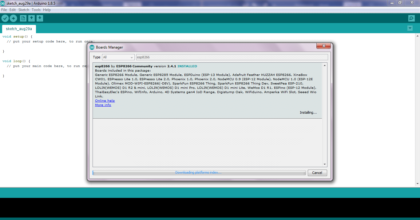
Fig. 35: Boards Manager in Arduino IDE - Scroll down, select the ESP8266 board menu and install “esp8266 by Esp8266 community”.
- Select your ESP8266 board from Tools > NodeMCU 1.0 (ESP12E Module).
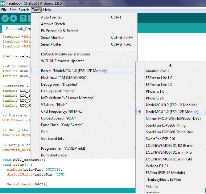
Fig. 36: Boards Selection in Arduino IDE Restart your Arduino IDE.
The Code
Download the Code from the link below and Open it in Arduino IDE.
Let’s understand the code.
Before uploading you need to make some changes in the code.
Place your Wi-Fi credentials here within the double quotes. The ESP8266WiFi.h library helps to run the functions of Wi-Fi in Arduino IDE.
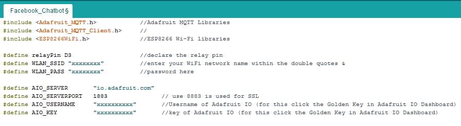
Now we will give our feed name to subscribe to our MQTT Server. For more details on MQTT refer here.
We will subscribe for MQTT in our Void Setup().
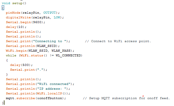
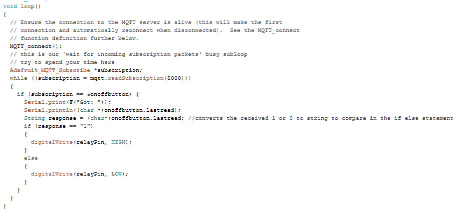
The relayPin is set as OUTPUT and initially Low. Now, we will play with this Output here in the Void Loop().
Save the Code and Upload it via the USB Cable. Do not forget to select the COM port from the Tools Menu in Arduino IDE before uploading the code.
Connections
Flow the circuit diagram for connecting the home automation.
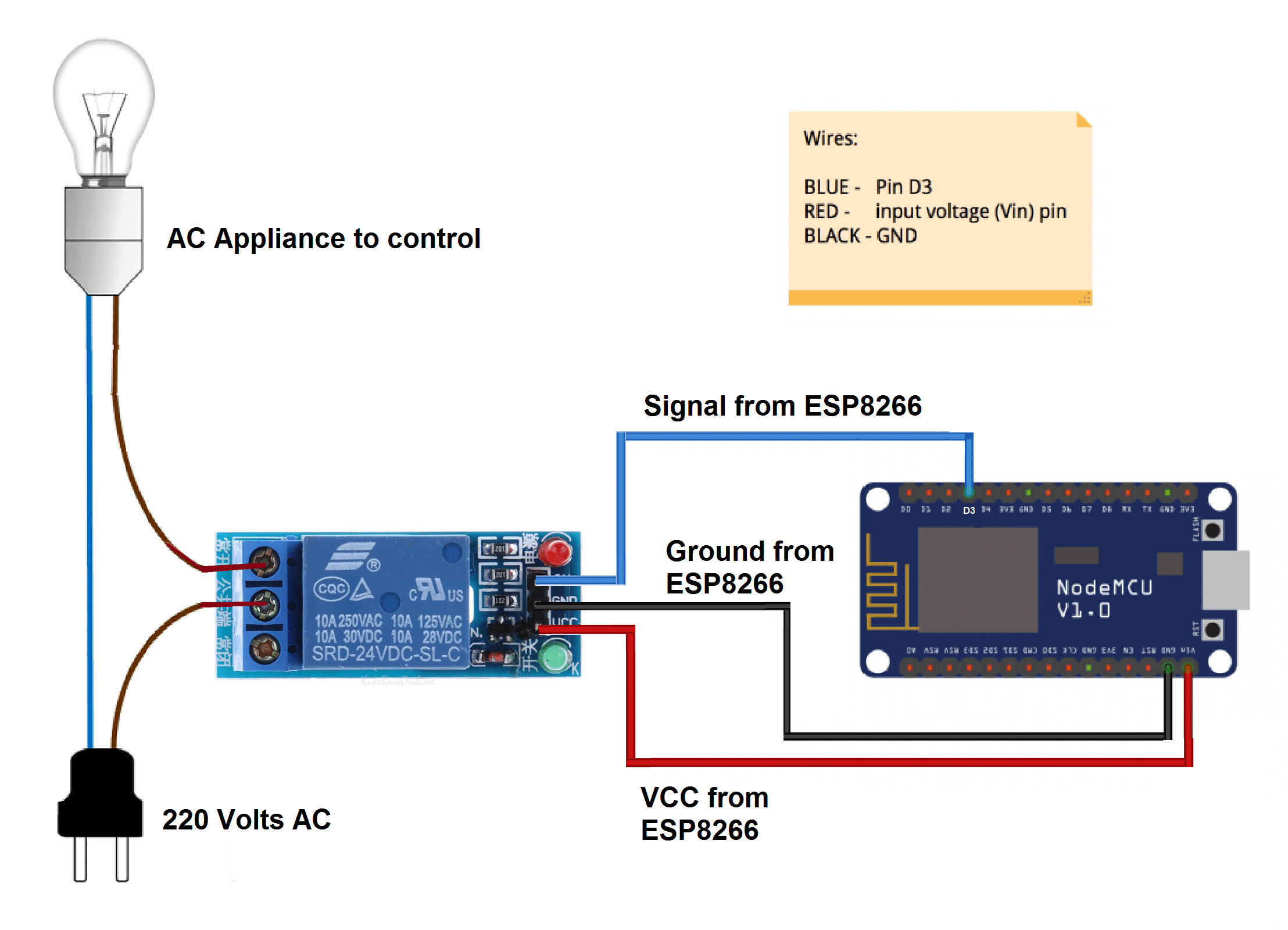
Now, power up everything.
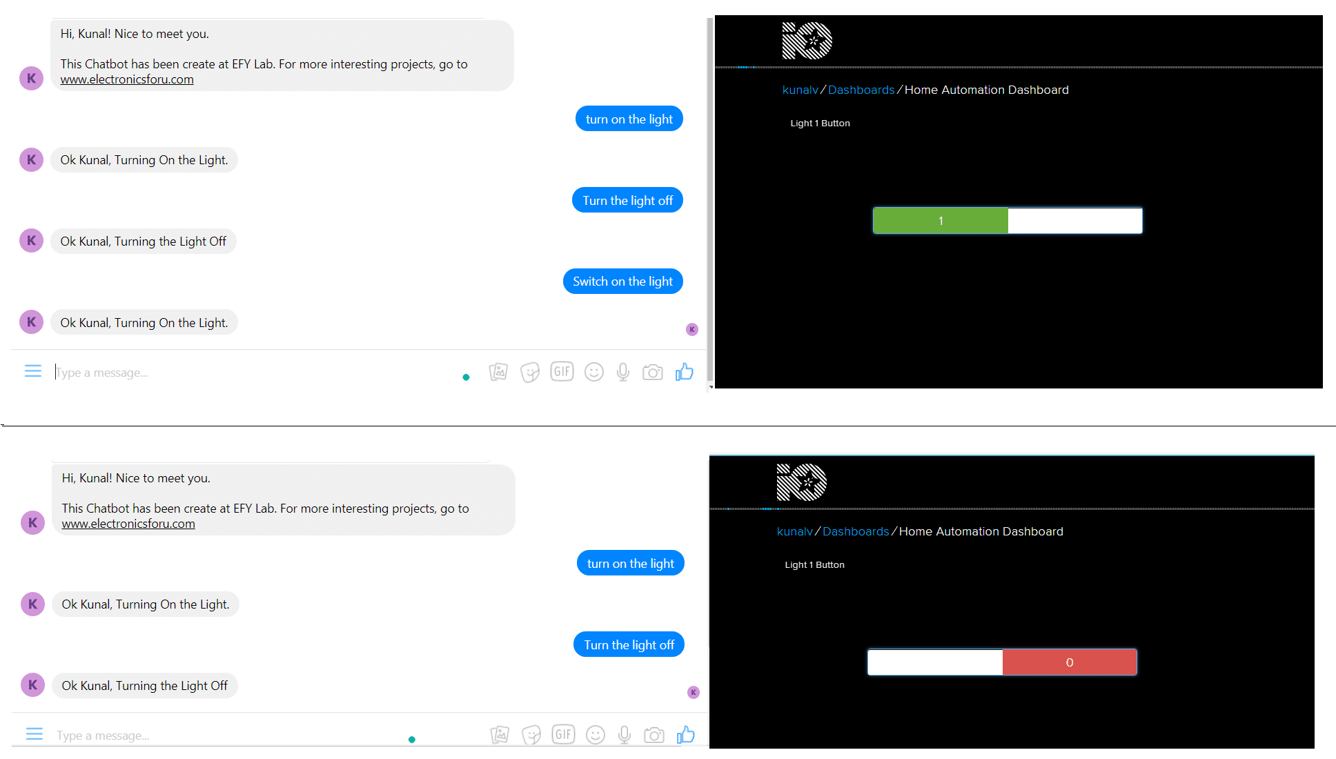
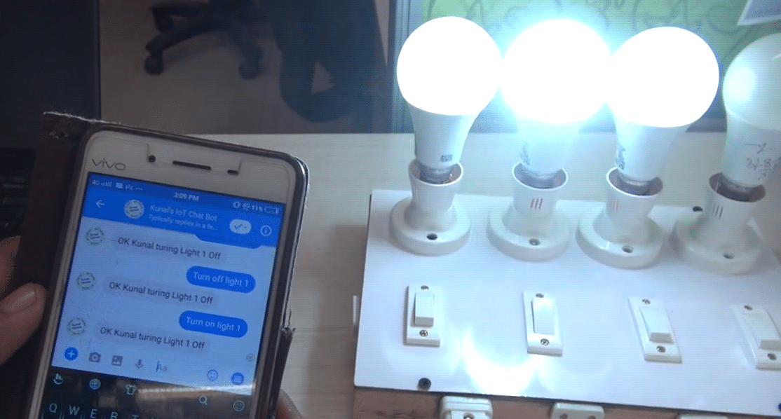
Open Messenger App on your phone, search the chatbot with its name and start chatting with your IoT system by giving commands like “Turn on the light” or “Switch on the light”.
To download the source code click here.
To download the components for this project, visit kitsNspares.

Hi,
Thanks for the nice article.
i followed above steps but getting error while integrating chatfuel platform with ifttt server. Error is with JSON API plugin “unable to parse json” with url https://maker.ifttt.com/trigger//with/key//?value1=1 (please note i have changed event name and webhook trigger key). However same url is directly working from browser. Do i am missing any step?
Plz try with this link: https://maker.ifttt.com/trigger/with/key/?value1=1
bro do you find something relevant to solve this issue..because i also have the same issue
i did till json plugin….but after that I’m not able to chat with the bot and get the job done….pls help
hi….i used ifttt as a server and used adafruit io to control a switch using messenger and chatfuel….the ifttt side and the adafruit side is tested and working but when i add json to the block and add the url from ifttt, and when i use the chatbot in messenger…it first shows “this person isn’t available right now”, then after a few milliseconds it shows the block text to be displayed but after that it shows ” An error in JSON plugin has occured ” and gives an option to select “show error details” and when i click it, it again shows “this person isn’t available right now” for a few milliseconds and then finally shows “unable to parse json” i’m unable to figure out what the problem is…..can you guys help me out?
same issue with me as well
same issue with me as well. Do you have any solution for this problem.
same issue with me as well. Do you have any solution for this problem. Have you done with your project??
i had same issue. after a loong while it started to work.
my url looks like : http://maker.ifttt.com/trigger/xxxxx/with/key/yyyyyyy/?value1=0
* report plugin errors option was hooked so i unhook it
* modify plugin default phrases changed to blank
good now!
is it working fine with this URL?
I am goint to start this project. Are you available if I need any help?
hi,will this project work?can i contact you if i have any issues??
I am not blue color plus mark to create new block. What should I do now?
I have same issue. Do you have any solution for this problem. Have you done with your project??
I can test with Chatbot with Inbox section of Chatfuel. But Adafruit IO server will not get updated in real time.
please solve my problem by today.
Same problem the switch is not toggelling
Is any one of you got the output for this project?
the project work well just put the URL that you get from webhook instead of X and your event name instead of Y
https://maker.ifttt.com/trigger/PUT EVENT NAME HERE/with/key/PUT URL HERE/?value1=0
then you can copy this code in to your browser and it will work and then try it with chatbot.
If after you copy the code in chat bot it show error in jason plugin you should uncheck the tick wich say
Report plugin error in the boot
you can see it below the part that you copy the url in the chatbot
then everything works well
Hello, in chatfuel the AI respond to the word closer to what we have input to AI Rule, Is there is a way that bot respond to the identical word what we enter in AI rule box