


 This article describes a smart electronic counter that counts the number of pressure-cooker whistles and also time duration of the cooking. It triggers a buzzer alarm when the preset whistles count or preset cooking time duration is reached.
This design can also be used in factories having boilers with pressure release valves to automatically turn them off on hearing the sound at boiling point. Or it can be used in steam engines to automatically cut off power when sound is made by the vessel’s outlet valve.
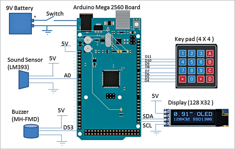

Block diagram of the project is shown in Fig. 1. The components used in the project are listed under the Bill of Material table.
Circuit and working
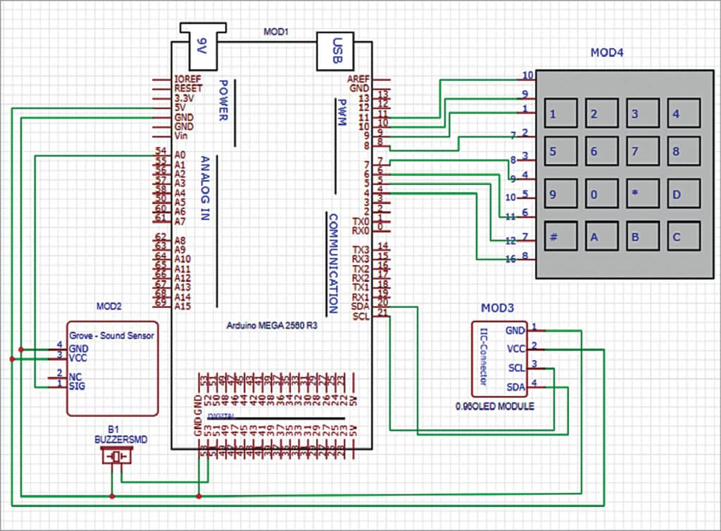
Circuit diagram of the smart whistle counter is shown in Fig. 2. The circuit comprises Arduino Mega 2560 board (MOD1) and LM393 based sound sensor module (MOD2), which is used for detection of the whistle’s sound.

It operates at 5V and produces an analogue voltage proportional to the sound level. This voltage is given to analogue input pin (A0) of microcontroller MOD1.
The 4×4 keypad is used as an input device to set the total number of whistles required, or total time duration for cooking. The keypad has keys arranged in four rows and four columns, which are connected to eight digital input pins of the microcontroller.
The 23mm (0.91-inch) I2C serial pin 4 of the OLED display module is interfaced with Arduino. It displays the number of detected whistles and time duration. The resolution of the display is 128×32 and its driving voltage is 5V. It is connected to the SCL and SDA pins of the Arduino board.
Active alarm buzzer (B1) used in this project works on 5V. It is connected to digital output pin 53 of Arduino board MOD1. It provides 1kHz sound signal. The buzzer is triggered when the preset whistle count or the preset cooking duration is reached.
| Bill of Material | ||
| Component | Part Number | Quantity |
| Microcontroller board | Arduino Mega 2560 (MOD1) | 1 |
| Sound sensor | LM393 (MOD2) | 1 |
| Display | 23mm OLED 128×32 (MOD3) | 1 |
| Keypad | 4×4 keypad (MOD 4) | 1 |
| Buzzer | MH-FMD ( B1) | 1 |
| On off switch | S1 | 1 |
| Battery | 9V battery | 1 |
Software
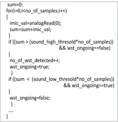
The sound sensor MOD2’s output pin 1, connected to analogue input A0 (pin 54) of microcontroller MOD1, is digitised with 10-bit resolution. A moving window low-pass filter is implemented in software with the window size of 25,000 samples. The sum value of window is compared with the ‘high threshold’ and a whistle is declared detected if the sum value is higher. The whistle sound stays high for a few seconds.
Whistle low detection is also important. If the detected flag is true and window sum value is less than the ‘low threshold,’ whistle low is declared. This section of the C code is shown in Fig. 3.
This method of whistle detection is very robust. It works well even in presence of other household noises.
The other functionalities of software include running the clock timer (minutes and seconds), getting inputs from the 4×4 keypad, displaying data on the OLED, and sounding the buzzer. The display shows the number of detected whistles and time since start of the cooking process.
Working of the circuit is simple. Before using, set the number of whistles you want and time required for cooking using the keypad. Place the device somewhere near the stove.
When the number of whistles reaches the preset value, the buzzer sounds to indicate that the task of the pressure cooker is over and it is time to turn off the stove. If the pressure cooker does not sound any whistle for a long period of time, then also it sounds the buzzer, after the preset cooking time. This could happen when there is some issue with the pressure cooker because of which it did not sound the buzzer.
You can upload the code to Arduino using the IDE by selecting the right port of Arduino and board model.
Construction and testing
Upload source code (smart_kitchen_v4.C) of the project on Arduino Mega 2560 board (MOD1). Then wire up the circuit as per the circuit diagram shown in Fig. 2.
Place the device near the cooking stove and, using the keypad, set the number of whistles you want. You may now start the cooking on stove. When the device detects the set number of whistles, it alerts you to turn off the stove.
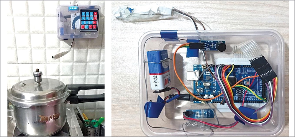
The author’s prototype’s external and internal views are shown in Fig. 4.
Download source code
Palak Patel is an electronics engineer having experience in embedded system development for terminal automation industry. Currently she is doing freelancing for embedded systems projects

how can i download the source code?
The source code is present at the end of the article.
My grandmother needs this asap. Cool prototype.
Great , Thnaks