There are at least two popular applications of blinking a string of 110V/230V AC incandescent lamps. The first is audio-visual warning at construction sites or where repairing is going on. The second is to express joy and excitement during holidays like New Year’s Day.
Here we use a very simple and low-cost timer NE555 to switch on and off two output loads alternately for audio and visual indications. You can achieve this by using a bipolar-transistor-based NE555 or CMOS-based LMC555.
This circuit can be made to blink AC lamps at a low frequency, or switch on and off electrical loads connected to the mains at a low speed. In order to reduce the RF emissions, switching is done only at zero crossings of the mains AC voltage.

The switching frequency is selected according to the resistor and capacitor components connected to NE555. It can be varied using 100-kilo-ohm potmeter VR1.
Circuit and working
Circuit diagram of the AC lamp blinker is shown in Fig. 1. It is built around a step-down transformer (X1), 9V voltage regulator 7809 (IC1), timer NE555 (IC2), two MOC3043 optoisolators (IC3 and IC4), two BTA06 triacs (Triac1 and Triac2), two 1N4007 diodes (D1 and D2), six LEDs (LED1 through LED6), two piezo-buzzers (PZ1, PZ2), two 230V AC, 60W bulbs (Load1 and Load2), and a few other components.
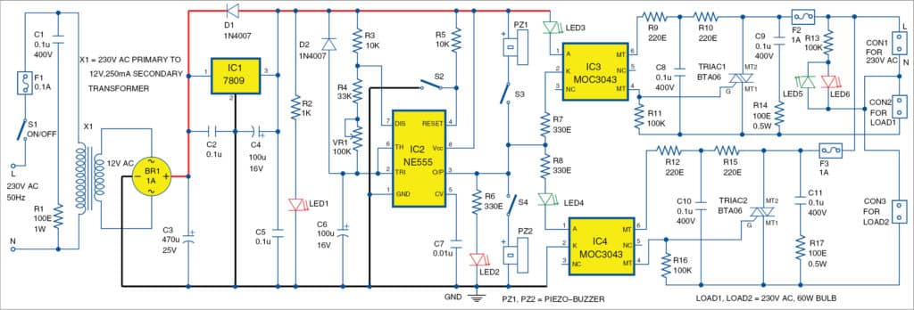
Power supply
The circuit works off a 9V regulated power supply derived from transformer X1, bridge rectifier BR1 and regulator 7809. Alternatively, you can use a 6V-15V DC or 6V rechargeable battery after slight modification in the circuit.
The resistors in series with all LEDs should have appropriate values depending on the power supply voltage and the type of LEDs. Piezo-buzzers PZ1 and PZ2 should be used with internal oscillator and should be operational at the selected power supply.
Oscillation frequency of timer NE555 is set with R3, R4, potmeter VR1 and capacitor C6. Frequency F is obtained at output pin 3 of IC2 as per the following relationship:
F=1.44/[{R3+2×(R4+VR1)}×C6]
The output of timer NE555 drives piezo-buzzers (PZ1 and PZ2), which can be switched on and off using switches S3 and S4, respectively. It also drives two LEDs (LED3 and LED4) and MOC3043 optoisolators (IC3 and IC4) with zero-crossing detectors.
When the output of timer IC2 is low, piezo-buzzer PZ1, LED3, IC3, Triac1 and Load1 are activated. In that case, Load2 is switched off. When the output of timer IC2 is high, piezo-buzzer PZ2, LED4, IC4, Triac2 and Load2 are activated. In that case, Load1 is switched off.
That is, Load1 and Load2 are activated alternately and the time of their activation is controlled by timer NE555. Timer NE555 is isolated from the AC mains using optoisolators so that you can change the frequency of the loads and blinking ratio without the danger of AC mains.
The circuit does not have critical components and is operational immediately after proper assembly. However, precaution should be taken as the circuit drives loads directly connected to the AC mains. That makes it obligatory to use optocouplers or optoisolators like MOC3041, MOC3042 or MOC3043. You may also use optocouplers rated for 600V, like MOC3061-M, MOC3062-M or MOC3063-M.
You may use triacs compatible with the required loads and the selected optocouplers. When working with 230V or 240V AC mains, you need to use at least 400V rated triacs, and preferably 600V rated triacs like BT139-600, BTA06-600, TIC226M and MAC223A8.
Resistor and capacitor circuits around triacs reduce the noise and protect the triacs. These are obligatory and should be selected according to the local conditions of the mains and the selected components including the loads.
Carefully select the values of resistors and capacitors connected directly to the mains. These should support the maximum possible voltages observed in the local AC mains voltage.
Construction and testing
An actual-size PCB layout of AC lamp blinker using timer NE555 is shown in Fig. 2 and its components layout in Fig. 3. After assembling the circuit on the PCB, enclose it in a suitable box. Place transformer X1 inside the box and connect its primary and secondary (12V AC) wires shown in the PCB. Connect 230V AC mains power supply across L (live) and N (neutral) terminals. Fix fuses, switches and potmeter VR1 on the front side of the box.


Connect Load1 and Load2 across CON2 and CON3, respectively. Fix piezo-buzzers PZ1 and PZ2 on the back side of box. Also fix the LEDs at any appropriate location outside the box for visual indications.
Depending on the loads, use heat-sinks with thermal resistance equal to or below 30ºC/W for Triac1 and Triac2.
Download PCB and component layout PDFs: click here
Note
The circuit should be used only with appropriate fuses. It is preferable to first test the circuit through an isolation transformer connected to the AC mains and with light loads like a 230V, 15W bulb. Also, it is preferable to first test at lower AC voltage like 50-100Vrms. Check for short-circuits or other anomalies before initial testing of the circuit with AC mains.
Caution
As there is risk of electrical shock (the extreme left and right of the PCB shown by the dotted lines), this circuit should be tried only by qualified personnel familiar with the operations of triacs and AC mains.
Petre Tzv Petrov was a researcher and assistant professor in Technical University of Sofia, Bulgaria and expert-lecturer in OFPPT(Casablance), Kingdom of Morocco. Now he is working as an electronics engineer in the private sector in Bulgaria.
This article was first published on 27 January 2018 and was updated on 9 January 2021.