


 Air-coolers provide cool air in a room by adding moisture to the air. This moist air is blown inside the room by an exhaust fan or blower, which makes the room temperature drop. These coolers require frequent refilling of water. Presented here is a circuit to refill water automatically in an air-cooler tank when the water drops below a predetermined level.
Circuit and working
Circuit diagram of the automatic water refiller for air-coolers is shown in Fig. 1. It is built around NE555 timer (IC1), transistor BC547 (T1), reed switches (S1 and S2), and a few other components. IC1 is configured similar to bi-stable mode, the only difference being that switch S1 is connected to pin 6 instead of pin 4.
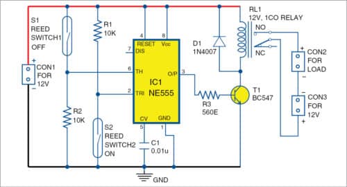
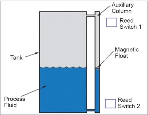
The two reed switches (S1 and S2) are affixed at upper and bottom levels of the tank as shown in Fig. 2. The working of the circuit is pretty simple.

If water drops below the predetermined level, the magnetic float closes reed switch S2 to pull pin 2 of IC1 to ground. Thereby the voltage on pin 2 goes below 1/3Vcc and the output of IC1 goes high. This energises the relay to activate the solenoid valve. Thus the water flows into the tank.
When the tank is full, the magnetic float closes reed switch S1. Pin 6 of IC1 goes above 2/3Vcc and the output goes low. This de-energises the relay to deactivate the solenoid valve, which stops the water flowing into the cooler tank.
Construction and testing
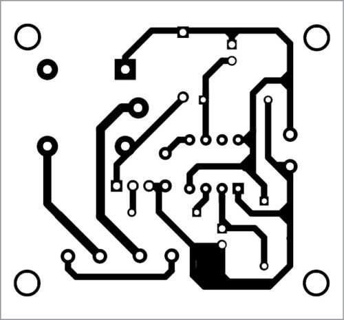
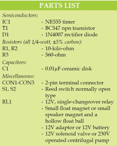
A PCB layout of the automatic water refiller for air-coolers is shown in Fig. 3 and its components layout in Fig. 4. Assemble the circuit and enclose it in a suitable cabinet.

Download PCB and component layout PDFs: click here
The water tank of an air-cooler has two holes—drain outlet and overflow outlet. Level-sensing arrangement for the water tank is done as follows: Attach a small-diameter PVC pipe to the tank (refer Fig. 2) between the two outlets. Put a magnetic float inside the PVC pipe. Affix one reed switch on the pipe near the drain outlet and the other reed switch near the overflow outlet.
The magnetic float can be made using a small speaker magnet and a hollow float ball. The diameter of the magnetic float should be slightly less than the PVC pipe’s so that it can float freely from bottom to top, or vice versa, based on the water level. If possible, fit the pipe in the tank’s inner wall with reed switches affixed externally.
Note
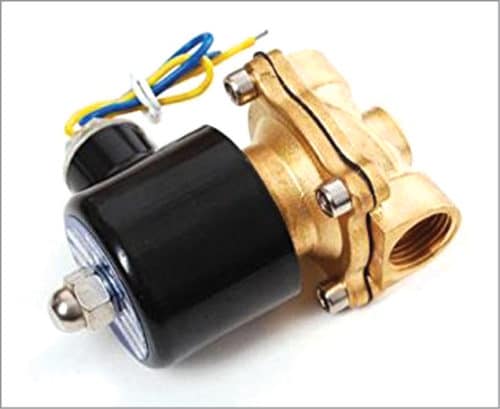
If the load is a 12V solenoid valve as shown in Fig. 5, use 12V DC supply to power the circuit and the load. Alternatively, use 230V AC supply at CON3 and external 12V adaptor at CON1, if the load is a 230V centrifugal pump.
Please suggest us where can we get the components from online easily.
You can check our website https://grab.electronicsforu.com/
But the link is not working