


 A good bench power supply is the most vital equipment for electronics engineers and hobbyists. However, bench power supplies used in R&D labs are costly. Output rating is also a major issue. A variable DC supply up to 30V with a few amperes current is the basic requirement for labs.
Making a power supply for use in labs is not an easy task due to the complexity of the circuit. To provide high current outputs, it needs heavy transformers and semiconductor devices. A simple alternative is to use a computer power supply unit (PSU). With some modifications, the PSU can be turned into a good bench power supply.
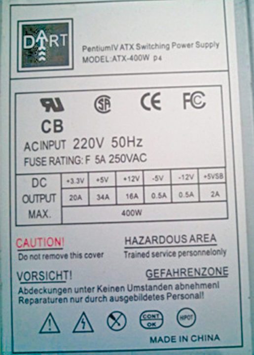
Fig. 1 shows input and output ratings of an ATX computer PSU. The available outputs are +3.3V (20A), +5V (34A), +12V (16A), -5V (0.5A), -12V (0.5A) and +5VSB (2A).

These outputs are available on one 20-pin Molex connector (some newer PSUs have 24-pin connector) and four various other 4-pin connectors.
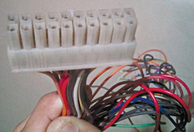
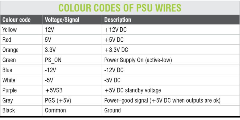
A 20-pin Molex connector is shown in Fig. 2. Wire colour codes of standard ATX PSU connector are shown in the table below. From the table, you can identify voltage outputs corresponding to different colour codes.

Power up and testing
To test a computer PSU without connecting it to the motherboard, short its green wire to any of the black wires (ground wires). The power supply’s cooling fan should turn on to indicate that the power supply is ‘on.’ Now you can check the voltages of all the different wires with respect to black wire by using a multimeter. If all the voltages are as per the colour code table, the power supply is working fine.
Another method is to check the voltage of grey wire, which is a PGS or power-good signal. It should be +5V approx.
Opening the power supply unit
As you know, computers work on 230V AC power. To open the PSU enclosure, first disconnect its 230V supply cord. After you unscrew the PSU enclosure and remove the cover, be careful of large capacitors on the PCB. Wait for a while or discharge them using a proper discharging tool. Otherwise, you run the risk of getting an electric shock from capacitors.
You will see that all the same-colour wires are bundled together and soldered in one place on the PCB. The PCB is also marked with legends for their voltage and signals.
Modifications
Fixed outputs:
Since the outputs available on various PSU connectors are meant for connections to the motherboard, the connections need to be slightly modified for use of the unit as a bench power supply.
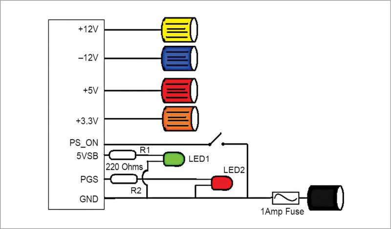
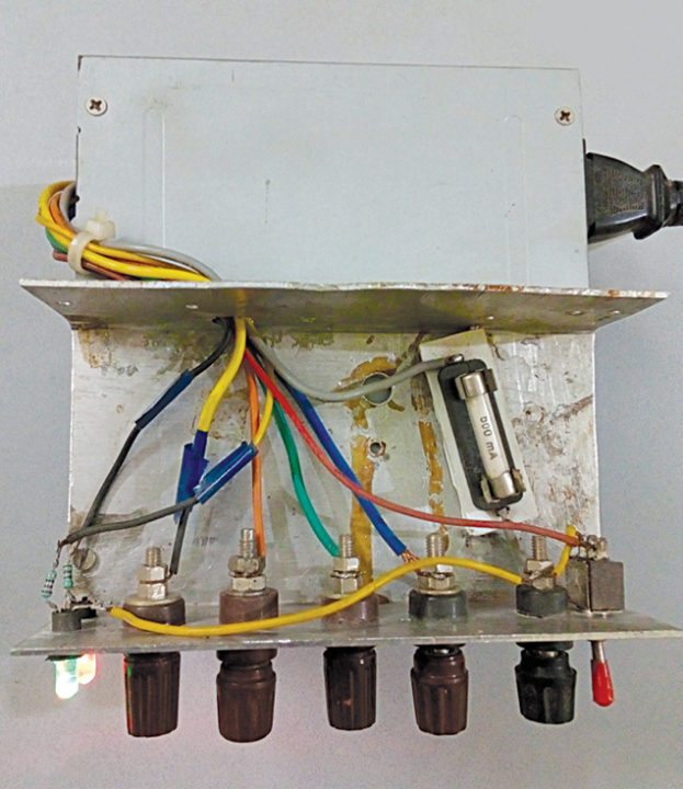
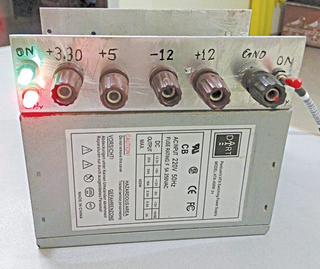
All the required connections for fixed but multiple outputs are shown in Fig. 3 and the author’s prototype of the same is shown in Fig. 4. front panel of the author’s prototype is shown in Fig. 5.
Power-on switch:
The green wire in ATX is PS_ON or ‘power supply on’ wire. It is used by the motherboard to turn on the PSU. Normally, its voltage level is +5V DC. To turn on the PSU, it needs to be grounded. So you need to connect an on/off switch between PS_ON and ground.
Standby indicator:
When AC power cord is plugged into 230V AC socket and power switch is in ‘off’ position, the PSU is in standby mode. To provide an indication for standby mode, connect an LED to purple wire, which provides a 5VSB signal from ATX PSU. 5VSB is active-high when the PSU is in standby mode. The voltage level of 5VSB is +5V DC, so you need to connect a 220-ohm, 0.25-watt resistor in series with the LED. As soon as power switch is operated to power-on the PSU, 5VSB goes low and the LED stops glowing, indicating that the PSU is in power-on mode.
Power-on indicator:
For power-on indication, you need to connect an LED to grey wire through a 220-ohm, 0.25-watt resistor. This grey wire provides PGS or power-good signal. In standby mode, this signal is active-low. After powering up the PSU, it becomes active-high (+5V DC).
Series fuse:
You may ask what’s the need of a series fuse when the PSU has a very good inbuilt short-circuit protection. The fuse is used here not to protect the PSU but your valuable project.
As you know, the current rating of the PSU is moderately high at more than 10 amperes. But in general, an average electronics project or circuit doesn’t need such high current. If there is any short circuit in your project, the short-circuit current will reduce to the level of the fuse current. Without a fuse, the short-circuit current will reach the maximum output current of the PSU, severely damaging the circuit.
To make your bench power supply more effective, remove the PCB board from the PSU enclosure. Place it in a larger enclosure and mount banana sockets for different outputs. You can also use an ammeter in series with the output to measure the load current on board.
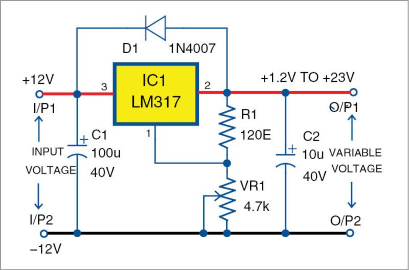
Variable output power supply
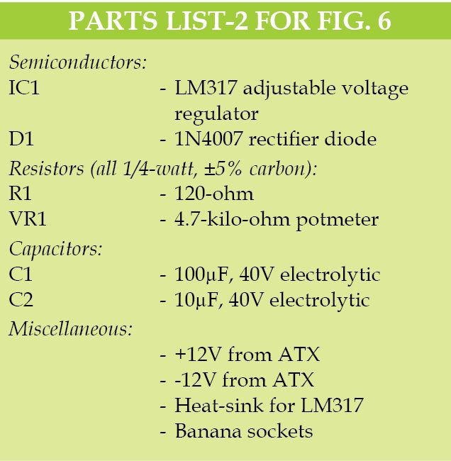
To convert the PSU into a variable power supply, use an LM338K or LM317 adjustable voltage regulator IC as shown in Fig. 6. Connect +12V and -12V supplies from the PSU to this circuit so that you get 1.2V to +23V maximum output using VR1 potmeter. But the current output will reduce to 500mA because the output current of -12V output is 500mA only.
Construction and testing
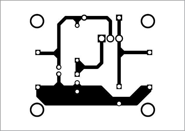
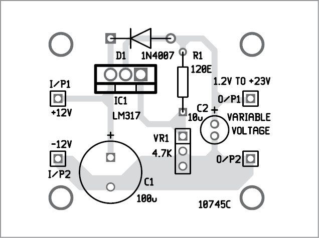
An actual-size PCB layout for variable power supply is shown in Fig. 7 and its components layout in Fig. 8. Some tips for testing the power supply are:
1. Some newer PSUs come with a current-sense wire. If the wire is grey in colour, connect it with +3.3V. If it is pink, connect it with +5V supply.
2. Make sure that you are using an ATX power supply. If it is an older one, it will have different colour codes for the wires. If you don’t have the actual colour code data, don’t try anything.
Download PCB and component layout PDFs: click here
3. If the LEDs do not light up, check these for correct polarity.
4. The cooling fan in the PSU may make noise. As the PSU is not powering a load continuously, you can limit the fan speed to reduce the noise. You can do so by reducing the supply voltage from 12V to 5V. Consequently, if the PSU heats up abnormally, reconnect the fan with 12V supply.
5. It is recommended to connect a separate fuse for each output.
Advantages of PSU
1. Very effective short-circuit protection
2. Thermal protection
3. Earth fault protection
4. Compact size with respect to voltage and current output ratings
5. Very cheap compared to conventional a bench power supply.
Disadvantages
1. Complex circuit, difficult to repair without adequate knowledge
2. SMD soldering station may be required for repair

good project and information
5 yr before i tried it and it was success project when i have taken +5v ,12v and 3v frm SMPS. Then i made a 15 A 0-24v regulator and connected its input to the smps (-12 -and+12) it worked for a small duration then explored with a big bang … i checked and understood 2 power transistors were blown then i have taken another SMPS board and that also explored withi in seconds . How ever i felt one improvement in the second explosion that its mosfet also blown along with power transistors. It was an unforgettable power supply (myself renamed it as UPS) for me . LOL…. 😀 how ever thank you .
I have a 450 atx smps (zebronics make) which recently became totally dead. On opening the cover, I found all components are through hole with not a single SMD component. Please publish DIY on how to repair this type of smps with all through hole components.